

Seat apparatus
- Summary
- Abstract
- Description
- Claims
- Application Information
AI Technical Summary
Benefits of technology
Problems solved by technology
Method used
Image

Examples
Embodiment Construction
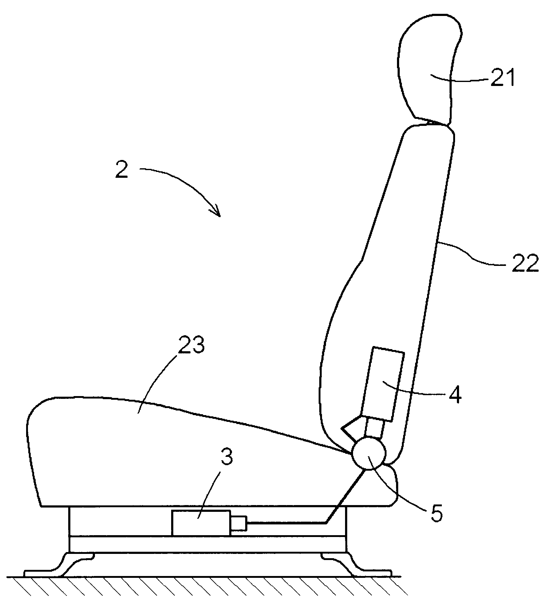
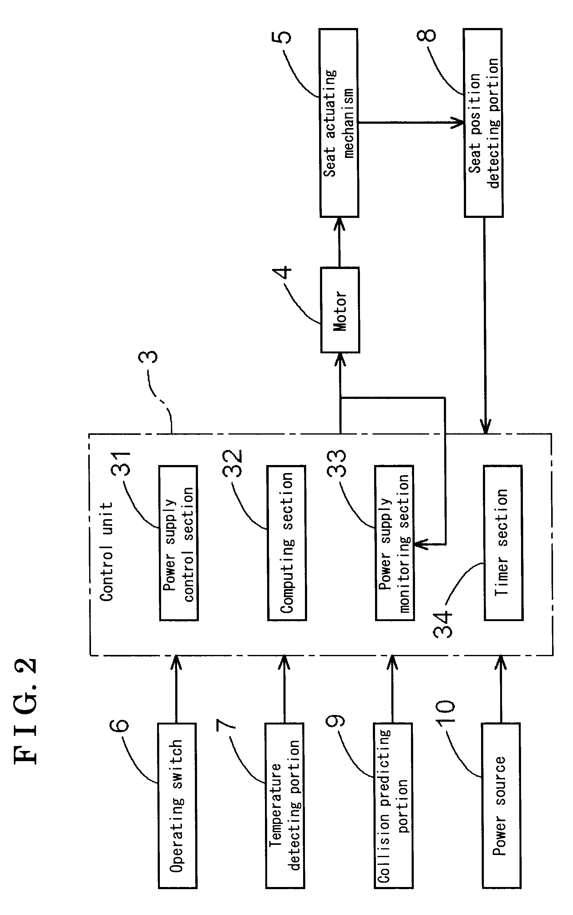
[0013]An embodiment of the present invention will be explained with reference to the illustrations of the figures as follows. FIG. 1 is a schematic view illustrating a seat apparatus according to the embodiment. Further, FIG. 2 is a functional block diagram schematically illustrating the seat apparatus of the embodiment. As shown in FIGS. 1 and 2, the seat apparatus includes a seat 2 adapted to be arranged on a floor of a vehicle, an operating switch 6 commanding the seat 2 to and not to move, a control unit 3 controlling the movement of the seat 2, a motor 4 driving the seat 2, and a seat actuating mechanism 5 transmitting a driving force of the motor 4 to the seat 2.
[0014]When a passenger presses the operating switch 6 to activate the motor 4, the motor 4 drives the seat 2 to move, so that a position of the seat 2 is adjusted. Accordingly, the passenger adjusts a position of the seat 2 to a desired position according to the activation of the operating switch 6 pressed by the passe...
PUM
 Abstract
Description
Claims
Application Information