Electronic device and power supply

a technology of electronic devices and power supplies, applied in the direction of dc-dc conversion, energy industry, efficient power electronics conversion, etc., can solve the problems of increasing the volume of the power supply, increasing the material cost, and generating excess heat in the power supply, so as to reduce the duty ratio, increase the duty ratio, and shorten the time

Active Publication Date: 2021-01-21
SAMSUNG ELECTRONICS CO LTD
View PDF0 Cites 4 Cited by
  • Summary
  • Abstract
  • Description
  • Claims
  • Application Information

AI Technical Summary

Benefits of technology

[0009]The controller may be further configured to reduce the duty ratio to shorten a time in which both the first switching element and the second switching element are at an On-state based on a level of voltage of the rectified power increasing over time, and increase the duty ratio to lengthen the time in which both the first switching element and the second switching element are at an On-state based on the level of the voltage of the rectified power decreasing over time.
[0010]The controller may be further configured to increase the duty ratio to lengthen a time in which both the first switching element and the second switching element are at an On-state based on a magnitude of current of the rectified power increasing according to a state of a load, and decrease the duty ratio to shorten the time in which both the first switching element and the second switching element are at an On-state based on the magnitude of the current of the rectified power decreasing according to the state of the load.

Problems solved by technology

In this case, the circuit configuration for correcting the power factor requires a plurality of elements, for example, a plurality of inductors, which leads to an increase in the volume of the power supply, and an increase in the material cost.
In addition, due to operation of the plurality of elements, excess heat may be generated in the power supply.
Also, the disclosure is not required to overcome the disadvantages described above, and an embodiment of the disclosure may not overcome any of the problems described above.

Method used


Image

  • Electronic device and power supply
  • Electronic device and power supply
  • Electronic device and power supply

Examples


Embodiment Construction

[0045]Embodiments will be described with reference to the accompanying drawings. However, the disclosure is not limited to the embodiments described below, but may be implemented in several forms and may be variously modified. A description for these embodiments is provided only to make the disclosure complete and allow those skilled in the art to which the disclosure pertains to completely recognize the scope of the embodiments. In the accompanying drawings, sizes of components may be enlarged as compared with actual sizes for convenience of explanation, and ratios of the respective components may be exaggerated or reduced.

[0046]It will be further understood that the term “connect” or its derivatives refer both to direct and indirect connection, and the indirect connection includes a connection over a wireless communication network.

[0047]The terms used herein are for the purpose of describing the embodiments and are not intended to restrict and / or to limit the present disclosure. F...


PUM


Abstract

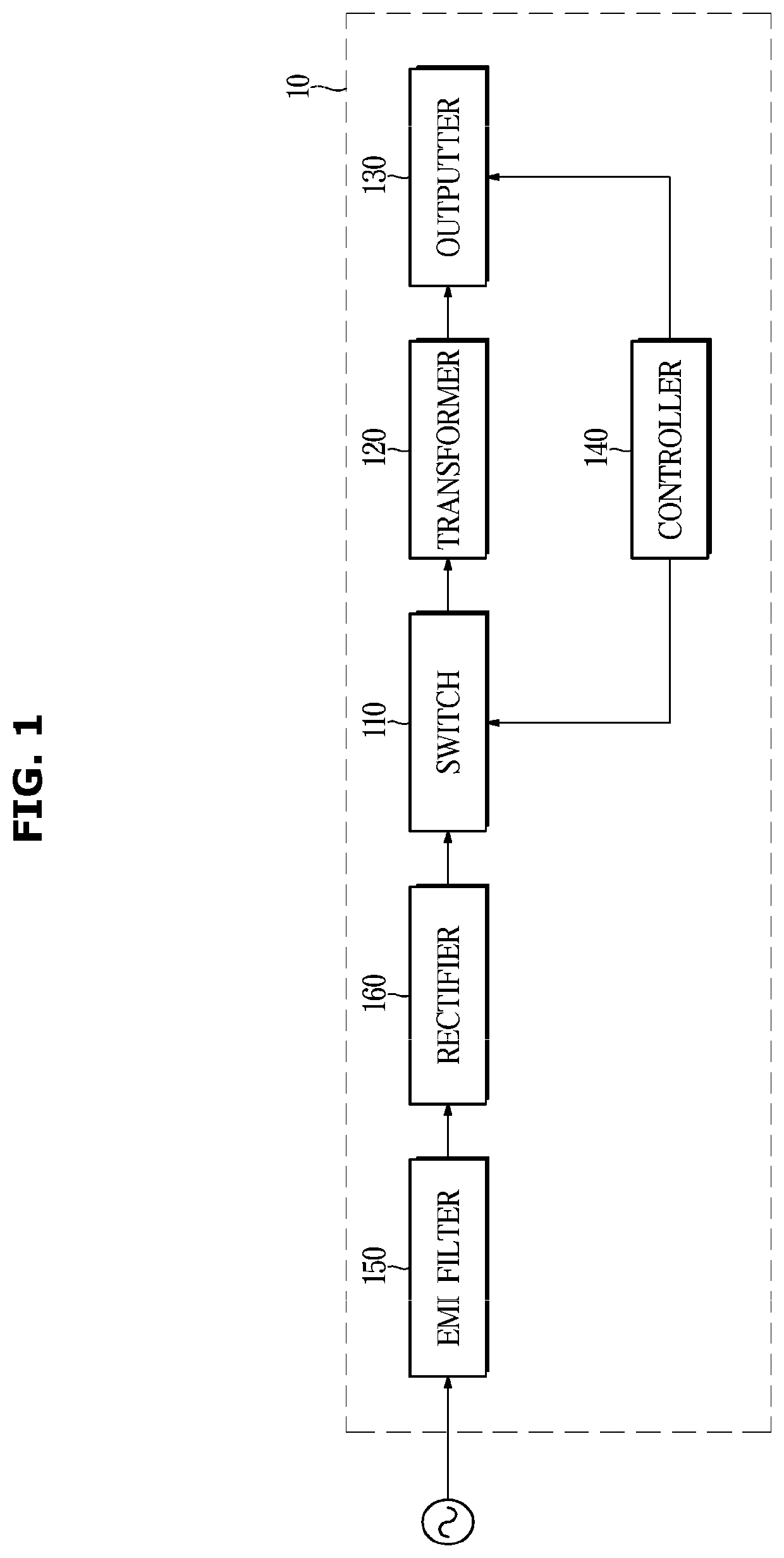
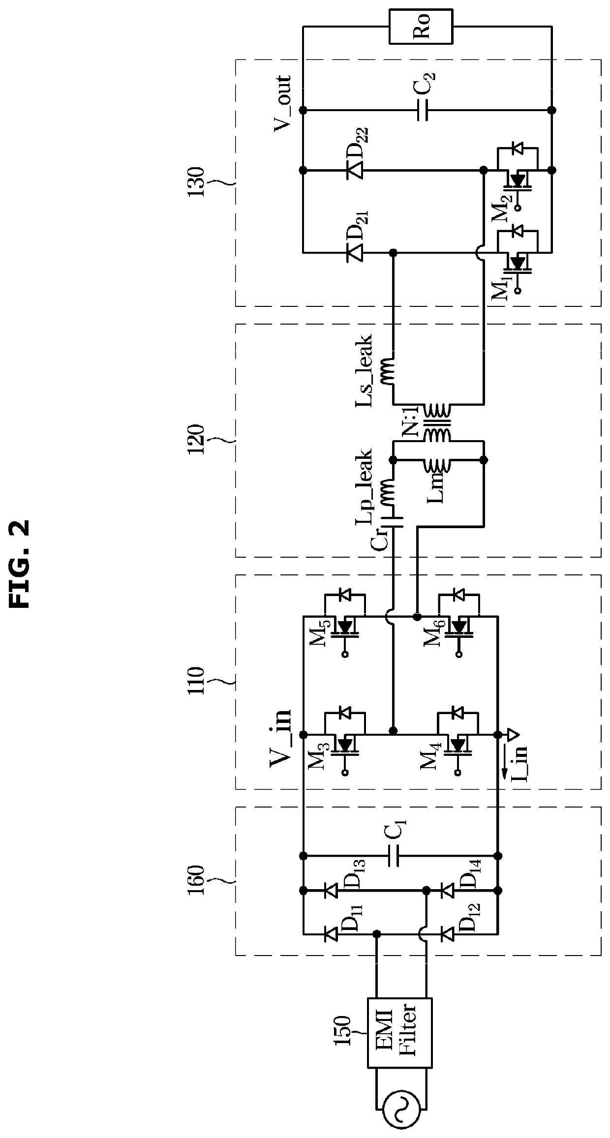
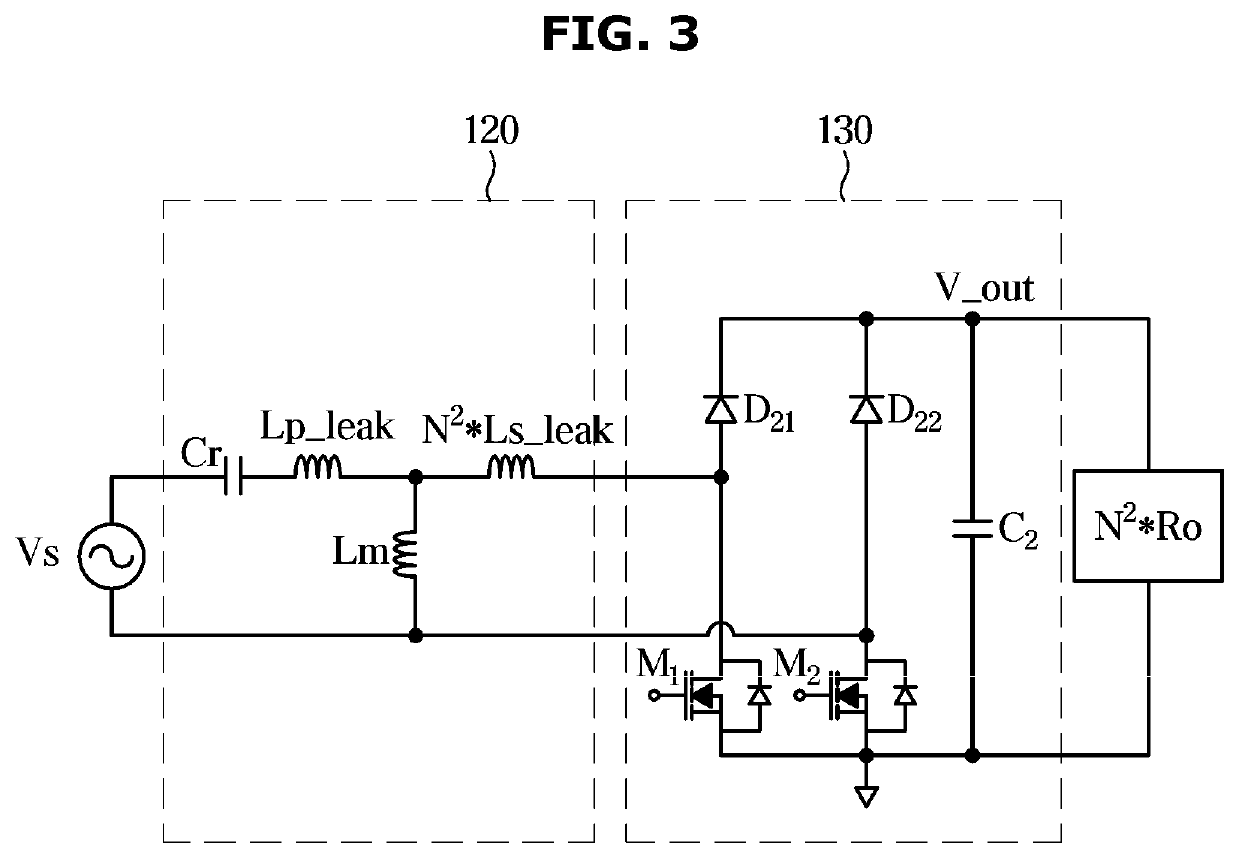
A power supply is provided. The power supply includes: a switching module including switching elements and is configured to receive rectified power; a transformer configured to transform first power received from the switching module; an outputter including first and second switching elements, and is configured to receive the transformed first power from the transformer and output an output voltage that follows a preset reference voltage; and a controller configured to control the switching module to operate in a full bridge mode or a half bridge module based on a peak voltage of the rectified power, adjust a switching frequency of the switching module based on the output voltage, control switching of the first and second switching elements based on the output voltage, and adjust a duty ratio of each of the first and second switching elements based on the rectified power.

Description

CROSS-REFERENCE TO RELATED APPLICATION[0001]This application is based on and claims priority under 35 U.S.C. § 119 to Korean Patent Application No. 10-2019-0087315, filed on Jul. 19, 2019, in the Korean Intellectual Property Office, the disclosure of which is incorporated herein by reference in its entirety.BACKGROUND1. Field[0002]The disclosure relates to a power supply for boosting a voltage while correcting a power factor, and an electronic device having the same.2. Description of Related Art[0003]In general, a power supply includes a separate circuit configuration for correcting a power factor to prevent reactive power generated according to a phase difference between voltage and current.[0004]For example, the power supply may include a separate circuit configuration for correcting a power factor in a converter that converts AC power into DC power.[0005]In this case, the circuit configuration for correcting the power factor requires a plurality of elements, for example, a plural...

Claims


Application Information

Patent Timeline
Patent Type & Authority Applications(United States)
IPC IPC(8): H02M7/219H02M7/217
CPCH02M7/219H02M7/2176Y02B70/10H02M1/4208H02M3/33576H02M1/0058H02M1/007Y02P80/10H02M3/33573H02M3/33571H02M3/01H02M3/33507H02M1/08H02M1/42
Inventor CHOI, YOUNGHOKIM, YOUNGSOOYOON, YOUNGNAMJUNG, SUNG-BUMCHOI, SHINWOOK
Owner SAMSUNG ELECTRONICS CO LTD
Why Eureka
Try Eureka