[0006]According to an aspect of the invention, there is provided a recording device including: a first suction unit which has a support member for supporting a recording medium and a plurality of suction holes provided in the support member to support the recording medium under control that a second suction force of the suction holes not covered by the recording medium is restricted to be smaller than a first suction force of the suction holes covered by the recording medium; a recording head which performs recording on the recording medium supported by the first suction unit; and a second suction unit which has a support member for supporting a recording medium and a plurality of suction holes provided in the support member and is disposed near the first suction unit in a transport direction of the recording medium and in which a third suction force of the suction holes not covered by the recording medium is set to be larger than the second suction force. Accordingly, an effect of
airflow on a flight state of ink droplets can be suppressed and floating of a recording medium from the support member can be sufficiently suppressed.
[0008]In the recording device, each of the first suction unit and the second suction unit may have a plurality of communication channels communicating a suction force generating section which generates a suction force for sucking air with the suction holes, and a suction force adjusting section provided to correspond to the suction holes and restricting the first suction force to be smaller than the second suction force, the
communication channel may have: a hole-side channel section which is closer to the suction hole than the suction force adjusting section; and a suction-side channel section which is closer to the suction force generating section than the suction force adjusting section, the suction force adjusting section may have: a diaphragm which is arranged between the hole-side channel section and the suction-side channel section and is displaced toward the hole-side channel section or the suction-side channel section by a
differential pressure between the hole-side channel section and the suction-side channel section; an open-close communication hole which is formed in the diaphragm, is opened and closed by the displacement of the diaphragm and communicates the hole-side channel section with the suction-side channel section in an opened state; and an
open communication hole which is formed in the diaphragm, is opened regardless of the position of the diaphragm and communicates the hole-side channel section with the suction-side channel section, and a hole
diameter of the
open communication hole disposed in the recording area may be smaller than a hole
diameter of the
open communication hole disposed on the upstream side of the recording area in the transport direction. Accordingly, a channel cross-sectional area of some of the communication channels communicating with the suction holes opened in the recording area can be made narrower than that on the upstream side or the downstream side of the recording area in the transport direction. As a result, a recording medium on the upstream side or the downstream side in the transport direction can be sufficiently sucked onto the support member to sufficiently suppress floating of the recording medium from the support member, and airflow generated in the recording area can be weakened to suppress an effect of the airflow on a flight state of ink droplets.
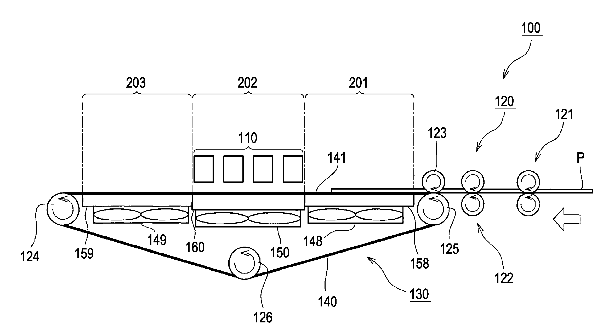
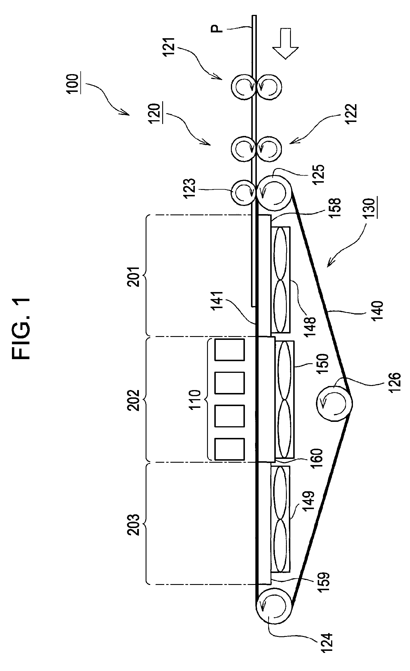
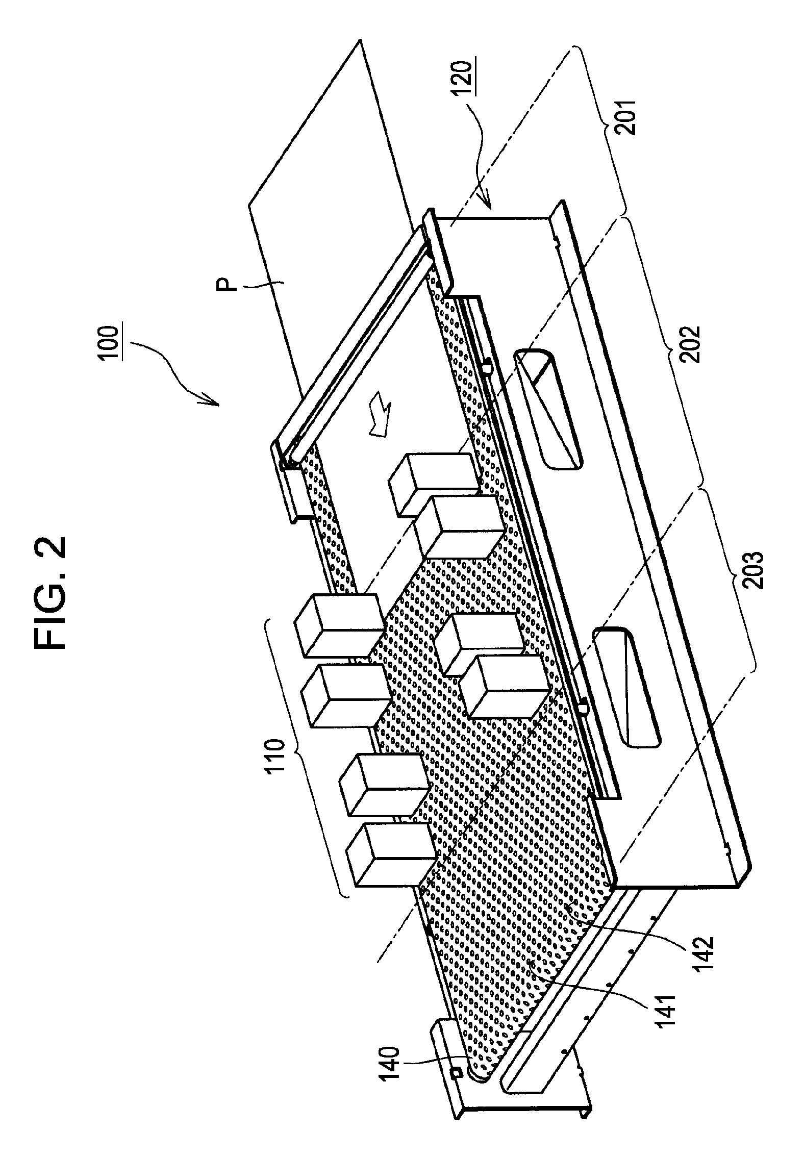
[0011]According to another aspect of the invention, there is provided a recording device including: a recording head which performs recording by ejecting ink on a recording medium; a transport member which has a plurality through holes formed therein to transport the recording medium to a recording area of the recording head; a suction unit which has a suction force generating section which generates a suction force for sucking air and a plurality of communication channels which communicate the suction force generating section with the through holes, and sucks the recording medium onto the transport member by generating a suction force in the through holes; and a suction force adjusting section which is provided to correspond to at least the through holes positioned in the recording area and restricts a suction force of the through holes opened to be smaller than a suction force of the through holes blocked by the recording medium, and by the suction force adjusting section, the suction force generated in the opened through holes positioned in the recording area can be made weaker than the suction force generated in the opened through holes positioned on the upstream side or the downstream side of the recording area in the transport direction. Accordingly, airflow generated in the recording area can be weakened to suppress an effect of the airflow on a flight state of ink droplets, and a suction force between a recording medium and the transport member on the upstream side or the downstream side of the recording area in the transport direction can be sufficiently ensured to sufficiently suppress floating of the recording medium at the stage where suction is started or after recording from the transport member.
[0012]In the recording device, when the through holes are blocked by a recording medium, the suction force adjusting section may increase a channel cross-sectional area of the communication channels communicating with the through holes, and when the through holes are opened, the suction force adjusting section may decrease a channel cross-sectional area of the communication channels communicating with the through holes. Accordingly, without controlling a drive force of the suction force generating section, the suction force of the through holes can be increased when the through holes are blocked by the recording medium, and the suction force of the through holes can be decreased when the through holes are opened.
[0014]In the recording device, some of the suction force adjusting sections may be disposed on the upstream side of the recording area in the transport direction. Accordingly, on the upstream side of the recording area in the transport direction, suction amounts from the opened through holes can be decreased without decreasing the suction force of the through holes blocked by the recording medium. Thus, on the upstream side of the recording area in the transport direction, floating of the recording medium from the transport member can be sufficiently suppressed and airflow generated in the opened through holes can be weakened to suppress an effect of the airflow on a flight state of ink droplets.

