Tracking determination based on intensity angular gradient of a wave

a technology of intensity angular gradient and tracking determination, which is applied in wave based measurement systems, direction/deviation determining electromagnetic systems, instruments, etc., can solve the problems of determining the accurate linear position and angular position (orientation) of the handheld device relative to the base station, unstable and significantly affected,

Inactive Publication Date: 2009-10-15
IDHL HLDG INC
View PDF56 Cites 58 Cited by
  • Summary
  • Abstract
  • Description
  • Claims
  • Application Information

AI Technical Summary

Benefits of technology

[0021]According to still another exemplary embodiment, there is a base station configured to communicate with a handheld device. The base station includes at least one emitter configured to emit a beam including an electromagnetic wave...

Problems solved by technology

While various technologies allow such a handheld device, determining the accurate linear position and angular position (orientation) of the handheld device relative to a base station or the device continues to be a problem.
Other technologies (see for example U.S. Pat. Nos. 7,188,045 and 7,353,134, the content of which are incorporate...

Method used


Image

  • Tracking determination based on intensity angular gradient of a wave
  • Tracking determination based on intensity angular gradient of a wave
  • Tracking determination based on intensity angular gradient of a wave

Examples


Embodiment Construction

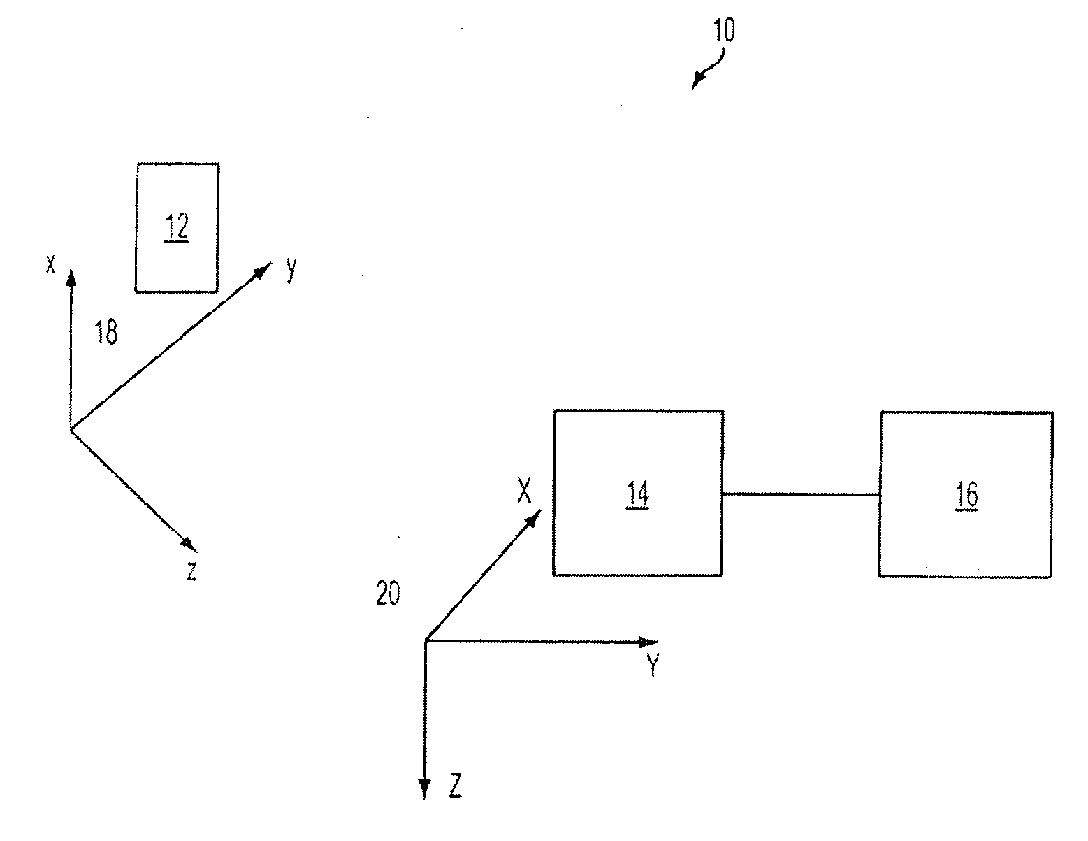
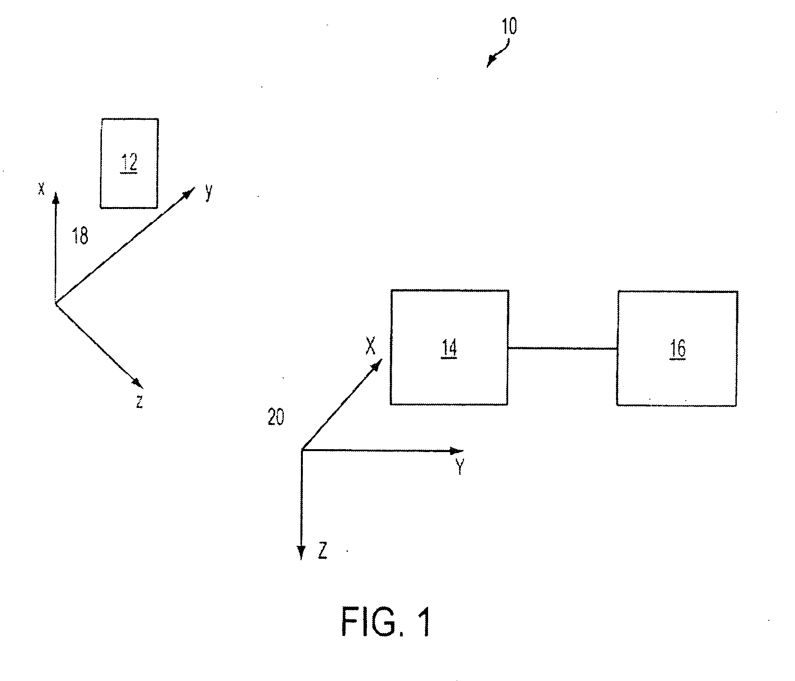
[0024]The following description of the exemplary embodiments refers to the accompanying drawings. The same reference numbers in different drawings identify the same or similar elements. The following detailed description does not limit the invention. Instead, the scope of the invention is defined by the appended claims. The following embodiments are discussed, for simplicity, with regard to the terminology and structure of infrared capable devices, i.e., infrared emitters and receivers. However, the embodiments to be discussed next are not limited to these systems but may be applied to other systems that use other forms of electromagnetic waves or non-electromagnetic waves such as acoustic waves.

[0025]Reference throughout the specification to “one embodiment” or “an embodiment” means that a particular feature, structure, or characteristic described in connection with an embodiment is included in at least one embodiment of the present invention. Thus, the appearance of the phrases “i...


PUM


Abstract

Handheld device, base station, computer readable medium and method for detecting a position of a handheld device. The method includes measuring intensities of at least one beam emitted by a base station; calculating relative intensities based on the measured intensities; and determining the position of the handheld device based on the measured intensities and the calculated relative intensities.

Description

RELATED APPLICATIONS[0001]This application is related to, and claims priority from, U.S. Provisional Patent Application Ser. No. 61 / 045,038 filed on Apr. 15, 2008, entitled “Tracking Determination Based on Relative Intensity Angular Gradient of Electromagnetic Wave,” the disclosure of which is incorporated entirely here by reference.TECHNICAL FIELD[0002]The present invention generally relates to tracking a linear position and an angular position of a device relative to a base station and, more particularly, to methods and techniques for tracking the linear position and the angular position based on an angular gradient distribution of an intensity of an electromagnetic wave generated by an electromagnetic source.BACKGROUND[0003]During the past years, the interest of having a handheld device, for example, a wand, pen, gaming device, remote control, mouse, etc., free of any wired link to a device, i.e., computer, TV set, game console, or other devices has increased. The users prefer to...

Claims


Application Information

Patent Timeline
IPC IPC(8): G06F15/00
CPCG01S1/70G01S5/16G01S3/782
Inventor LIBERTY, MATTHEW G.TANEN, JOSEPH S.
Owner IDHL HLDG INC
Why Eureka
Try Eureka