Method and apparatus for measuring distances using light

a technology of distance measurement and light, applied in the direction of distance measurement, instruments, television systems, etc., can solve the problems of high noise into the overall system, too complex lasers and optics in such approaches, and too expensive for budget limited or highly miniaturized applications, etc., and achieve the effect of convenient us

Active Publication Date: 2010-03-23
VORTANT TECH
View PDF25 Cites 27 Cited by
  • Summary
  • Abstract
  • Description
  • Claims
  • Application Information

AI Technical Summary

Benefits of technology

[0010](e) to provide a system to obtain images of distance data.
[0011]The present invention is a system for measuring the distance to an object, using light. The light intensity over multiple paths is measured, the paths being of differing optical length. The relative light intensity from the paths is used to calculate the distance to the object.
[0012]In one embodiment of the present invention, two or more light sources and one light detector are used. Light is sequentially transmitted from each source, and received at the light detector. In another embodiment of the present invention, one light source and two or more light detectors are used. Light is simultaneously received at both light detectors.
[0013]In another embodiment of the present invention, light is sequentially transmitted from two or more light sources, and an imaging device, such as a digital camera, is used to provide an array of distances containing distance information in each pixel.
[0014]In another embodiment of the present invention, a distance measurement device is attached to the finger or wrist of a person, and provides information on distances from the person to objects.
[0015]While the distance-measuring system of the present invention may be used to measure various distances from distances less than 10 centimeters in length to distances up to or greater than 5 meters in length, the distance-measuring system of the present invention provides an inexpensive, noncomplex, easy to use, distance-measuring system that is particularly well suited for measuring and / or monitoring distances to an object wherein the distance from the distance-measuring system to the object ranges from about 10 centimeters to about 5 meters. Over this preferred measurement range, the distance-measuring system of the subject invention has an accuracy of about ±10%.

Problems solved by technology

However, the lasers and optics in such approaches are too complex and expensive for budget limited or highly miniaturized applications.
Although such approaches use lower-cost LEDs and photodetectors, relatively short, properly shaped pulses are required.
These factors introduce higher levels of noise into the overall system, thus relatively complex electronics circuitry or specialized, high power pulse generation at the LED is needed.
The basic approach is subject to problems with range and reliability, and various improvements have been described in the following patents.
However, these approaches still require the use of lenses in order to obtain images of light spots or patterns.
The need for lenses increases the bulk as well as the cost of a distance-measuring system.

Method used


Image

  • Method and apparatus for measuring distances using light
  • Method and apparatus for measuring distances using light
  • Method and apparatus for measuring distances using light

Examples


Embodiment Construction

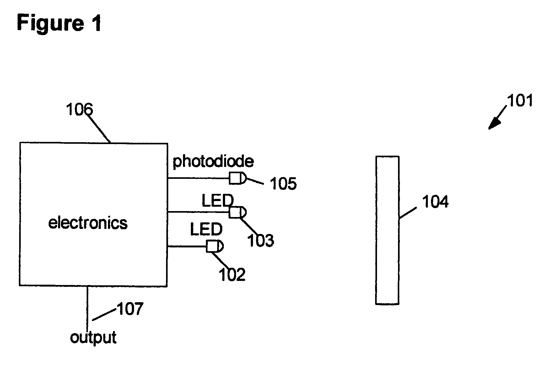
[0031]FIG. 1 is a block diagram of a preferred embodiment of a distance-measuring system 101 of the present invention, in which a “far” light source 102 and a “near” light source 103 are located at different distances from an object 104. Preferably, the light sources 102 and 103 have equal intensities and are LEDs (light-emitting diodes). Electronics 106 provides driving signals to sequentially illuminate the light source 102 and the light source 103. A light detector 105, preferably a photodiode, sequentially receives light from the light source 102 and the light source 103 that is reflected from the object 104. Preferably, the light sources 102 and 103 and the light detector 105 are located adjacent each other and contained in a single device. While for certain applications the light sources 102 and 103 need only be sequentially illuminated once, for other applications the light sources 102 and 103 are repeatedly illuminated sequentially for a selected period of time to obtain a d...


PUM


Abstract

A method and device for measuring a distance to an object with light determines the distance by measuring the relative intensity of light reflected from the object and traveling over two or more paths of differing optical length. Light is emitted by one or more light sources; reflected from a surface of the object; and the reflected light is detected by one or more light detectors. The light detector(s) generate signals based on the intensity of reflected light detected and the signals are utilized to calculate the distance from the device to the object.

Description

CROSS-REFERENCE TO RELATED APPLICATIONS[0001]This application is a continuation-in-part of copending U.S. patent application Ser. No. 10 / 641,850, filed Aug. 15, 2003, which claims the benefit of U.S. Provisional Application No. 80 / 405,079 filed Aug. 20, 2002 and also claims the benefit of copending U.S. Provisional Application No. 60 / 875,742, filed Dec. 19, 2006.GOVERNMENT LICENSE RIGHTS[0002]This invention was made with United States government support under one or more SBIR grants from the National Institutes of Health. The United States government has certain rights in this invention.BACKGROUND OF THE INVENTION[0003]The subject invention relates to a method and device for measuring a distance from the device to an object using light, and, more specifically, to a method and device for measuring a distance from the device to an object wherein light is emitted from one or more light sources of the device and reflected from a surface of the object to one or more light detectors of th...

Claims


Application Information

Patent Timeline
Patent Type & Authority Patents(United States)
IPC IPC(8): G01C3/08
CPCG01S7/491G01S7/4912G01S17/08G01S17/87H04N5/2226
Inventor SCHAEFER, PHILIP R.
Owner VORTANT TECH
Why Eureka
Try Eureka