
Wide-angle lenses with reduced ghost reflections

a wide-angle lens and ghost reflection technology, applied in the field of lenses, can solve the problems of secondary images appearing in the angle lens and more prone to ghost reflection in the wide-angle lens, and achieve the effect of reducing the intensity of secondary or ghost images

Active Publication Date: 2014-10-28
NING ALEX
View PDF11 Cites 28 Cited by
  • Summary
  • Abstract
  • Description
  • Claims
  • Application Information

AI Technical Summary

Benefits of technology

The present invention is about a wide-angle lens that reduces the intensity of a secondary or ghost image. The lens has three groups of lens elements, with the first group having negative power and a concave image surface. The second group has positive power and a concave image surface. The third group has positive power and a doublet lens design. The lens elements have profiles that out of focus the ghost images and anti-reflection coatings can be applied to reduce the intensity of the reflection. The lens design also satisfies certain conditions to correct chromatic aberrations. The lens has a field of view of 145 degrees or greater and a f# of about 2.8 or lower.

Problems solved by technology

A common fault of wide-angle lens is the appearance of secondary images.
Wide-angle lenses are more prone to have ghost reflections.

Method used


Image

  • Wide-angle lenses with reduced ghost reflections
  • Wide-angle lenses with reduced ghost reflections
  • Wide-angle lenses with reduced ghost reflections

Examples


examples 1-5

[0035]Examples 1 through 5 represents designs that all meet all of the conditional expressions (1) through (5) listed above.

example 1

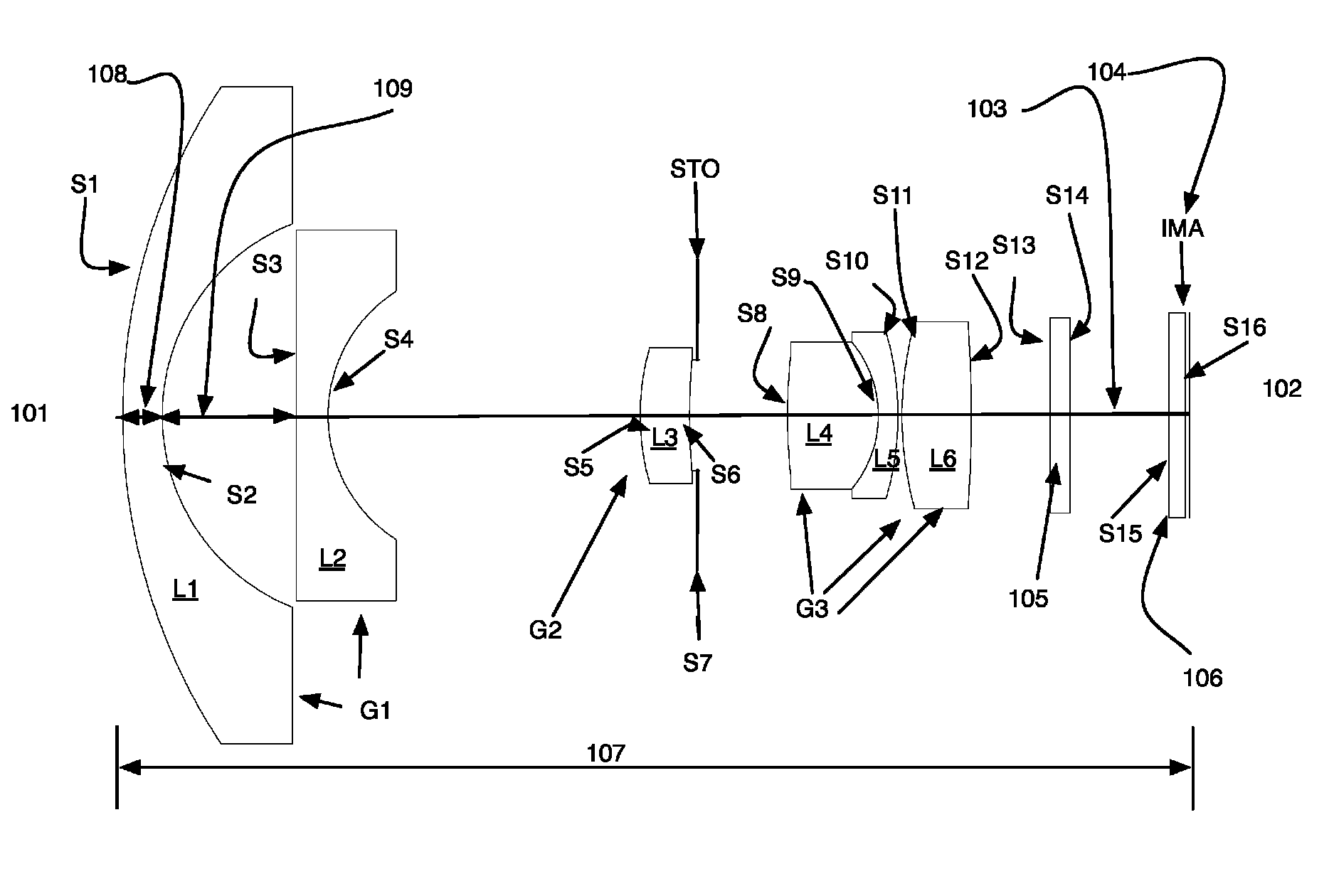
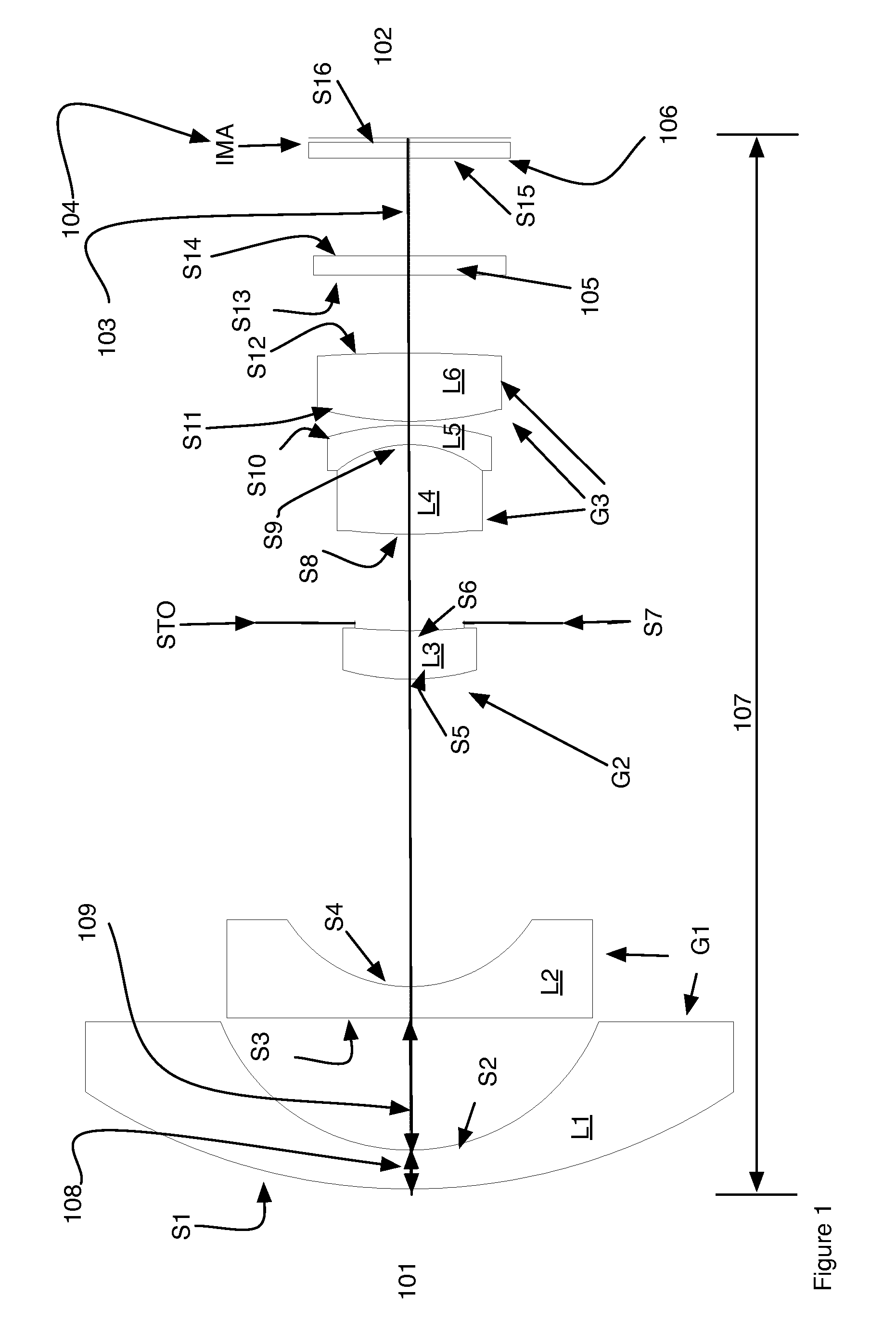
[0036]Still referring to FIG. 1 the optical layout of the first example is shown. Counting from the left side, which is also the object side 101 and proceeding to the image end 102, the wide-angle lens is comprised of lens elements L1-L6 arranged in three groups G1, G2, G3. The optical axes of the lens elements L1-L6 are aligned along the optical axis 103 of the wide-angle lens. In addition to the lens elements there is also an optical filter 105, a cover plate 106 for the image sensor 104 also labeled IMA. The image sensor 104 is located at the focal plane of the wide-angle lens. The total track length of the lens 107 is also shown. The first element L1 is a meniscus lens with negative power. The first element has a convex object surface S1 and a concave object surface S2. The second element L2 has negative power and a concave image surface S4. In preferred embodiments, this element L2 is a plano-concave element having a flat object surface S3. The third element L3 is a member of t...

example 2

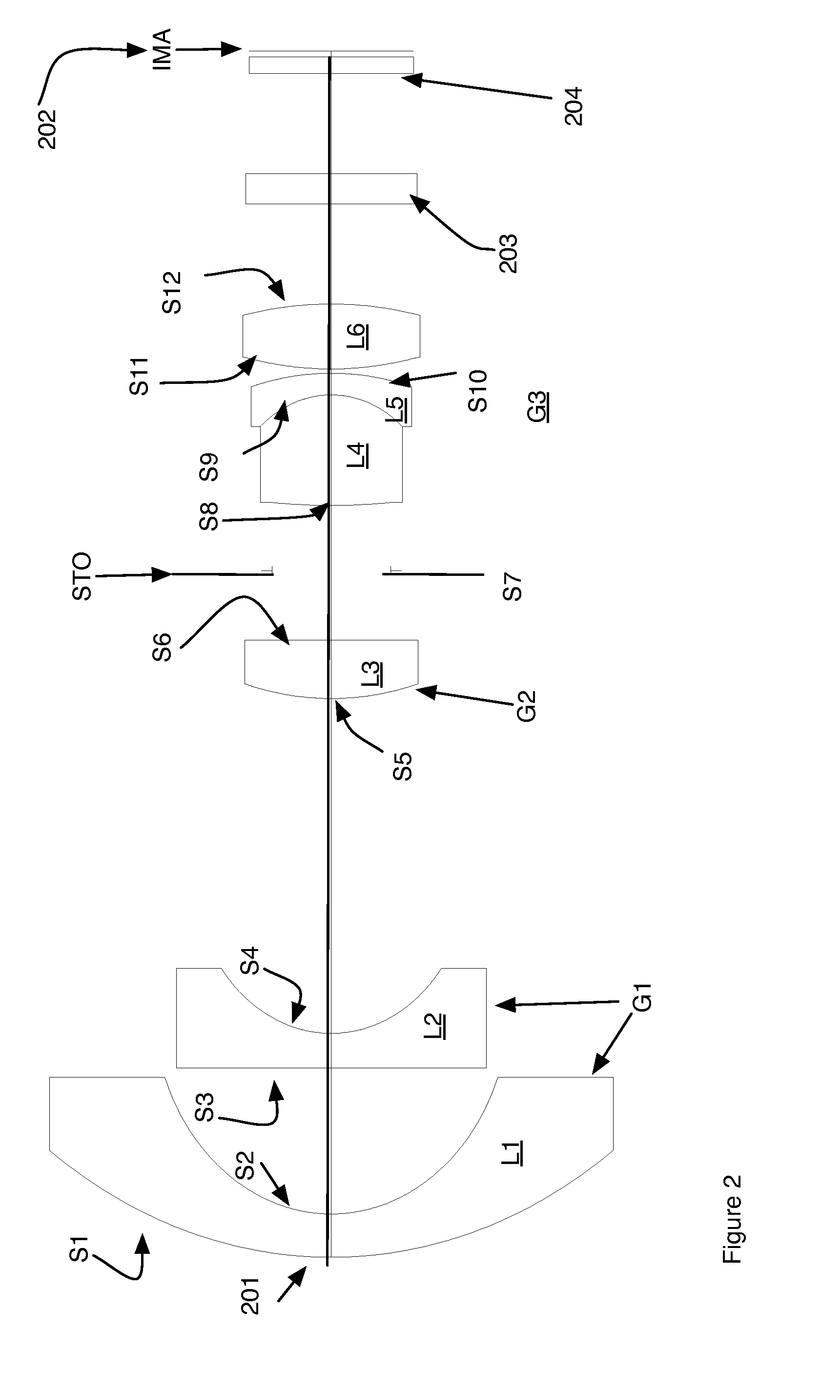
[0044]Referring to FIG. 2 a second exemplary embodiment is shown. Counting from the left side 201, which is also the object side, the first element L1 is a meniscus lens with negative power. The first element has a convex object surface S1 and a concave image surface S2. The second element L2 has negative power having a concave image surface S4. In preferred embodiments, this element is a plano-concave element having a flat object surface S3. The third element L3 has a positive power having a meniscus, plano-convex or double convex shape. In the example in FIG. 2, the third element L3 is plano-convex. The object surface is convex and the image surface S6 is planar. The aperture stop STO follows the 3rd element L3. The fourth element L4 and fifth element L5 form a cemented doublet where the power of the fourth element is positive and fifth negative. The image surface S10 of the fifth element is flat or convex. In the Figure shown it is convex. The object side S8 of the fourth element...


PUM


Abstract

Low ghosting wide-angle lens designs are presented. The dimensions and materials are selected such that the lens has a field of view of at least 145 degrees, f# of 2.2-2.9 and all secondary images of an object imaged on the image plane are focused such that they fall either outside of the image plane thus having a relative intensity that is less than 10−4 times the intensity of the primary image.In one embodiment a set of conditional expressions are all met. In another embodiment the conditional expressions are all met and the conditional expressions related to the physical size of the lens is narrowed. In another embodiment five and seven element designs are produced.

Description

CROSS-REFERENCE TO RELATED APPLICATIONS[0001]This application claims priority to U.S. Provisional Application 61 / 819,378 titled Wide-angle lenses with reduced ghost reflections, filed May 3, 2013 and to U.S. Provisional Application 61 / 723,712, titled Wide-angle lenses with reduced ghost reflections, filed Nov. 7, 2012 and to U.S. Provisional Application 61 / 837,398 titled Wide-angle lenses with reduced ghost reflections, filed Jun. 20, 2013. All of the Provisional applications are from the same inventor as this application and are currently pending.BACKGROUND OF THE INVENTION[0002]1. Technical Field[0003]The present invention relates to a lens system that reduces or eliminates ghost images.[0004]2. Related Background Art[0005]Digital imaging cameras use solid-state image sensors such as CCD or CMOS imagers to convert optical images into electronic signals. As the resolution of the imagers increases, there is a continuous need for optical lenses with increased performance. An importan...

Claims


Application Information

Patent Timeline
Patent Type & Authority Patents(United States)
IPC IPC(8): G02B27/00G02B9/08G02B9/00G02B13/04G02B13/06
CPCG02B13/06G02B13/04G02B27/0018
Inventor NING, ALEX
Owner NING ALEX
Learn More