Fluorescent substance, method of manufacturing the fluorescent substance, and light emitting device using the fluorescent substance
a technology of fluorescent substances and manufacturing methods, applied in the field of fluorescent substances, can solve the problems of low color rendering properties, poor chemical stability, and significant brightness decline, and achieve the effect of suppressing the occurrence of deviation in the ratio of color mixing with emission having different hues, less brightness reduction, and less brightness reduction
- Summary
- Abstract
- Description
- Claims
- Application Information
AI Technical Summary
Benefits of technology
Problems solved by technology
Method used
Image
Examples
examples 1 to 4
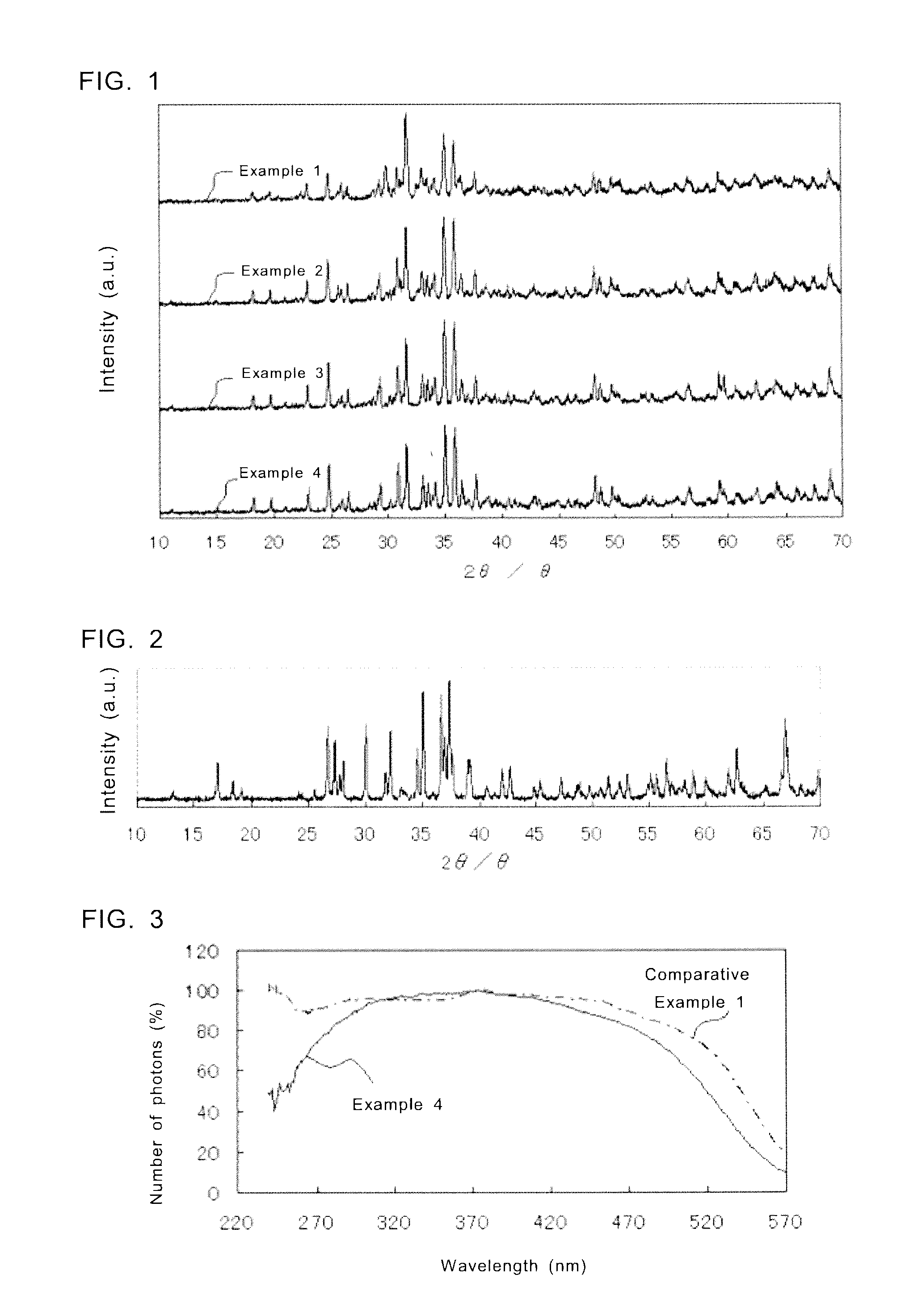
[0095]The feed composition ratio of the fluorescent substance according to Example 1 is Sr0.9Eu0.1Al2Si4ON7.33. Specifically, powders of SrCO3, AlN, Si3N4, and Eu2O3 were used as raw materials, and each raw material was weighed to satisfy the molar ratio of SrCO3:AlN:Si3N4:Eu2O3=0.9:2.0:1.33:0.1. More specifically, each raw material was weighed as shown below. Herein, the purity of each raw material of the fluorescent substance is assumed as 100%.[0096]SrCO3 . . . 15.84 g[0097]AlN . . . 9.77 g[0098]Si3N4 . . . 22.29 g[0099]Eu2O3 . . . 2.10 g
[0100]The weighed raw materials as described above were well mixed by dray ball milling, and then the mixture was loaded in a furnace and fired in a reducing atmosphere of nitrogen and hydrogen at about 1600° C. for about 20 hours. Thus, a fluorescent substance with the feed composition ratio of Sr0.9Eu0.1Al2Si4ON7.33 was obtained. An example of the reaction formula for generation of the fluorescent substance of Example 1 is shown in the Reaction...
examples 5 to 11
[0118]The fluorescent substances according to Examples 5 to 11 were obtained in the same manner as in Example 1, except that the raw materials were weighed to satisfy the predetermined feed composition ratios. In Examples 5 to 11, the feed composition ratios for SraAlbSicOdNe:Eu are changed within a range of (Sr+Eu):(Al+Si)=2:4.5 to 6.0. In Table 9, the measurement results of the feed composition ratio, chromaticity coordinates of emission color, brightness, and peak wavelength of emission spectrum of each fluorescent substance of Examples 5 to 11 are shown. Brightness shown in the table is a relative brightness with the brightness of the fluorescent substance of Comparative Example 1 as 100%.
TABLE 10PeakChromaticityBright-Wave-Feed CompositionCoordinatesnesslengthRatioxy(%)(nm)Exam-Sr0.9Eu0.1Al1.125Si3.375ON5.630.5490.44295.4609ple 5Exam-Sr0.9Eu0.1Al1.250Si3.750ON6.250.5390.45396.7601ple 6Exam-Sr0.9Eu0.1Al1.375Si4.125ON6.880.5380.454108.8601ple 7Exam-Sr0.9Eu0.1Al1.5Si4.5ON7.50.5360...
examples 12 to 17
[0122]The fluorescent substances according to Examples 12 to 17 were obtained in the same manner as in Example 1, except that the raw materials were weighed so that the concentration of Eu with respect to Sr becomes a predetermined concentration. Table 12 shows the measurement results of the feed composition ratio, Eu concentration, chromaticity coordinates of emission color, brightness, and peak wavelength of emission spectrum. Brightness shown in the table is a relative brightness with the brightness of the fluorescent substance of Example 15 as 100%.
TABLE 12Eu Peak ConcentrationChromaticity CoodinatesBrightnessWavelengthFeed Composition Ratio(%)xy(%)(nm)Example 12Sr0.96Eu0.04Al2Si4ON7.3340.4990.48667.7593Example 13Sr0.94Eu0.06Al2Si4ON7.3360.5150.47282.0594Example 14Sr0.92Eu0.08Al2Si4ON7.3380.5230.46594.4601Example 15Sr0.90Eu0.10Al2Si4ON7.33100.5300.459100.0601Example 16Sr0.88Eu0.12Al2Si4ON7.33120.5340.45595.3601Example 17Sr0.86Eu0.14Al2Si4ON7.33140.5290.45875.2602
[0123]Table 13 s...
PUM
 Abstract
Description
Claims
Application Information
 - R&D
- Intellectual Property
- Life Sciences
- Materials
- Tech Scout
- Unparalleled Data Quality
- Higher Quality Content
- 60% Fewer Hallucinations
Browse by: Latest US Patents, China's latest patents, Technical Efficacy Thesaurus, Application Domain, Technology Topic, Popular Technical Reports.
© 2025 PatSnap. All rights reserved.Legal|Privacy policy|Modern Slavery Act Transparency Statement|Sitemap|About US| Contact US: help@patsnap.com


