
Eye tracker and pupil characteristic measurement system and associated methods

a technology of pupil characteristic measurement and eye tracking device, which is applied in the field of eye tracking device for ophthalmic laser surgical system, can solve the problems of affecting the refractive outcome of surgery, affecting the accuracy of surgery, and the surgeon's reaction time is not fast enough to move the treatment laser in correspondence with eye movemen

Inactive Publication Date: 2006-07-20
ALCON REFRACTIVEHORIZONS
View PDF4 Cites 28 Cited by
  • Summary
  • Abstract
  • Description
  • Claims
  • Application Information

AI Technical Summary

Benefits of technology

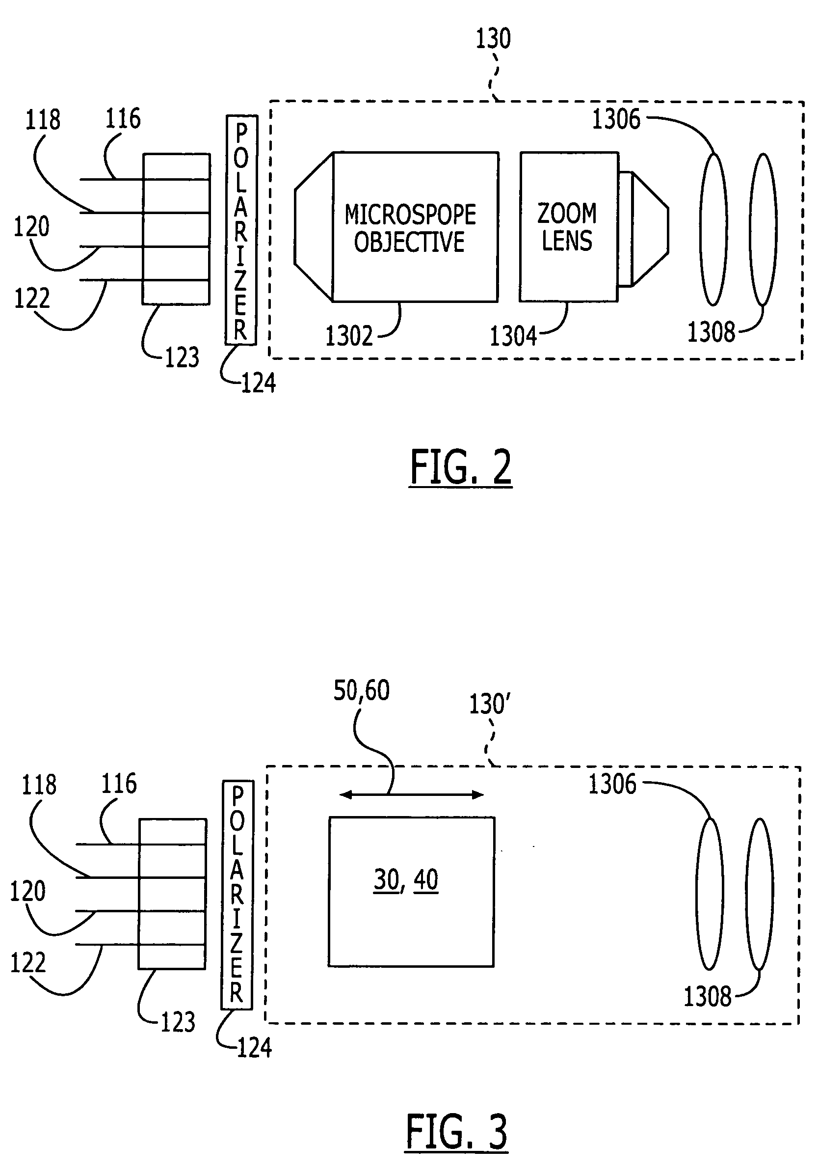
[0012] In both embodiments, means are provided for translating the prism along the optical axis between a first position wherein the light spots are separated by a first spacing and a second position wherein the light spots are separated by a second spacing that is smaller than the first spacing. The light spots thereby, in a preferred embodiment, have a substantially equal size with the prism in the first and the second positions.
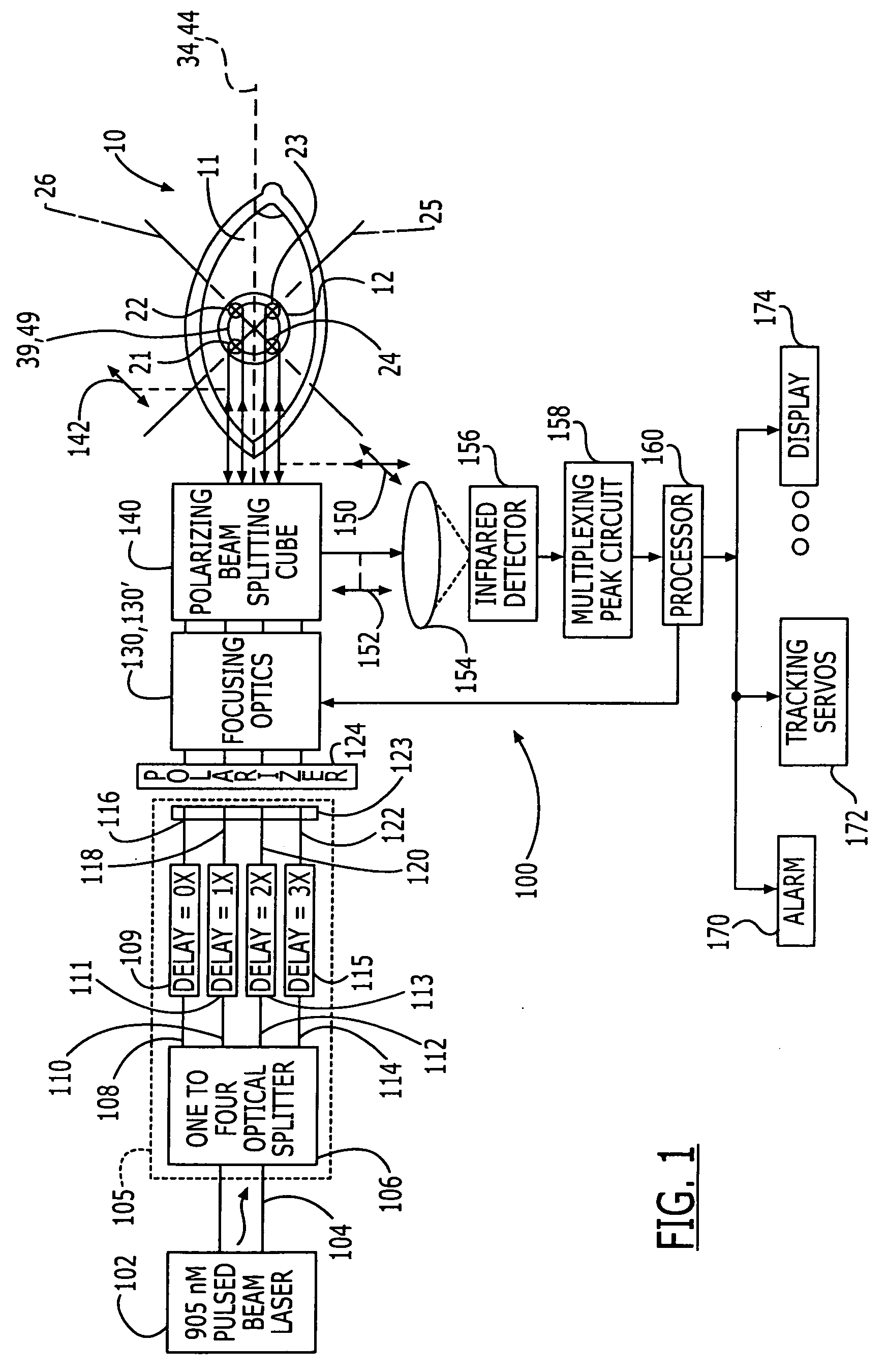
[0013] In a system incorporating the zoom mechanism of the present invention, a light source generates a modulated light beam, for example, in the near-infrared 905-nanometer wavelength region. An optical delivery arrangement including the zoom mechanism converts each laser modulation interval into the plurality of light spots, which are focused such that they are incident on a corresponding plurality of positions located on a boundary whose movement is coincident with that of eye movement. The boundary can be defined by two visually adjoining surfaces having different coefficients of reflection. The boundary can be a naturally occurring boundary (e.g., the iris / pupil boundary or the iris / sclera boundary) or a manmade boundary (e.g., an ink ring drawn, imprinted or placed on the eye, or a contrast-enhancing tack affixed to the eye). Energy is reflected from each of the positions located on the boundary receiving the light spots. An optical receiving arrangement detects the reflected energy from each of the positions. Changes in reflected energy at one or more of the positions is indicative of eye movement.
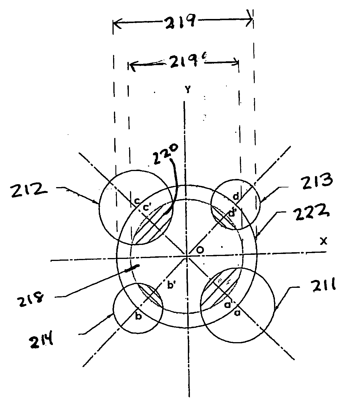
[0014] One aspect of the method of the present invention comprises a method for sensing eye movement. This method comprises the steps of directing a plurality of light beams onto a plurality of positions on a boundary defined by two adjoining surfaces of the eye to form a plurality of light spots. The two surfaces are selected to have different coefficients of reflection. Reflected energy from each of the plurality of positions is detected, wherein changes in the reflected energy at one or more of the positions is indicative of eye movement. In order to retain the light spots on the boundary, a size of a pattern formed by the plurality of light spots is adjusted on the plurality of positions. This adjustment, in a preferred embodiment, is performed without substantially changing a diameter of the individual light spots.

Problems solved by technology

In these procedures, surgical errors due to application of the treatment laser during unwanted eye movement can degrade the refractive outcome of the surgery.
However, this visual axis is difficult to determine, owing in part to residual eye movement and involuntary eye movement, known as saccadic eye movement.
Thus, even though a surgeon may be able to recognize some eye movement and can typically inhibit / restart a treatment laser by operation of a manual switch, the surgeon's reaction time is not fast enough to move the treatment laser in correspondence with eye movement.
However, a signal change can also be the result of external disturbances, such as a change in scattering characteristics from the ablated plume of tissue and the corneal surface during surgery.

Method used


Image

  • Eye tracker and pupil characteristic measurement system and associated methods
  • Eye tracker and pupil characteristic measurement system and associated methods
  • Eye tracker and pupil characteristic measurement system and associated methods

Examples


first embodiment

[0043] the zoom mechanism 30 comprises a pyramidal prism 31 having a plurality of, in a preferred embodiment four, reflective facets 32 (FIGS. 4 and 5). It will be understood by one of skill in the art that FIGS. 4 and 5 (and subsequently discussed FIGS. 6 and 7) are highly schematic representations in two dimensions for ease of presentation, four-sided pyramidal prisms being well known in the art.

[0044] The facets 32 meet at an apex 33 that points along an optical axis 34. It will also be understood by one of skill in the art that by “apex” is meant herein the point or sector at which the facets reach their smallest dimension, and that the prism may in fact comprise a truncated pyramid without a pointed apex.

[0045] An incident light beam 35 is directed onto each facet 32 of the prism 31 by an optical arrangement comprising a focusing lens 36 that is positioned to receive an incident light beam 35 and is adapted to image the respective incident light beam 35 to an image plane.

[004...

second embodiment

[0048] the zoom mechanism 40 comprises a pyramidal transmissive prism 41 having a plurality of, in a preferred embodiment four, facets 42 (FIGS. 6 and 7). The facets 42 meet at an apex 43 that points along an optical axis 44.

[0049] An incident light beam 45 is directed onto each facet 42 of the prism 41 by an optical arrangement comprising a focusing lens 46 that is positioned to receive an incident light beam 45 and is adapted to image the respective incident light beam 45 to an image plane.

[0050] Each incident light beam 45 refracted within the prism 41 to form a refracted beam 48 in a direction pointing toward the apex 43. The plurality of refracted beams 48, when incident upon a planar surface substantially normal to the optical axis 44, form the plurality of light spots 21-24 arrayed substantially in a square on an inscribed circle 49 (FIG. 1) about the optical axis 44.

[0051] The zooming mechanisms 30,40 further comprise a mechanism 50,60 for translating the prism 31,41 along...


PUM


Abstract

Systems and methods for tracking eye movement includes directing an incident light beam onto each facet of a pyramidal prism to produce a plurality of beams that form a plurality of light spots, at least two of the light spots having different diameters. The prism is translatable to effect a change in spacing of the light spots. Intensities of light reflected from the light spots is used to retain the light spots upon a pupil / iris boundary. A relative intensity of the spots indicates a change in pupil size. A second light spot positioned on a predetermined eye sector can also be used to calculate a pupil characteristic and an environmental effect on light received from the eye.

Description

CROSS-REFERENCE TO RELATED APPLICATION [0001] This application is a continuation-in-part of Ser. No. 10 / 156,654, filed May 28, 2002, entitled “Zoom Device for Eye Tracker Control System and Associated Methods,” the contents of which are incorporated hereinto by reference.FIELD OF THE INVENTION [0002] The invention relates generally to eye tracking devices for ophthalmic laser surgical systems, and more particularly to such a device that has a zoom capability. BACKGROUND OF THE INVENTION [0003] The use of lasers to erode a portion of a corneal surface is known in the art to perform corrective surgery. In the field of ophthalmic medicine, photorefractive keratectomy (PRK), phototherapeutic keratectomy (PTK), laser in situ keratomileus (LASIK), and laser epithelial keratomileusis (LASEK) are procedures for laser correction of focusing deficiencies of the eye by modification of corneal profile. [0004] In these procedures, surgical errors due to application of the treatment laser during ...

Claims


Application Information

Patent Timeline
Patent Type & Authority Applications(United States)
IPC IPC(8): G01P3/36A61B18/18
CPCA61F9/008A61F9/00804A61F2009/00846A61F2009/00872A61F2009/00897
Inventor CAMPIN, JOHN ALFREDKWON, YOUNG K.NGUYEN, PHUOC KHANHLI, HAIZHANGGRAY, GARY PAUL
Owner ALCON REFRACTIVEHORIZONS
Learn More