Vision Testing System

Active Publication Date: 2009-11-26
NIDEK CO LTD
View PDF6 Cites 4 Cited by
  • Summary
  • Abstract
  • Description
  • Claims
  • Application Information

AI Technical Summary

Benefits of technology

[0011]According to the subjective vision testing system of the invention, a

Problems solved by technology

However, such configuration having two LCDs and two polarization filters

Method used


Image

  • Vision Testing System
  • Vision Testing System
  • Vision Testing System

Examples


Example

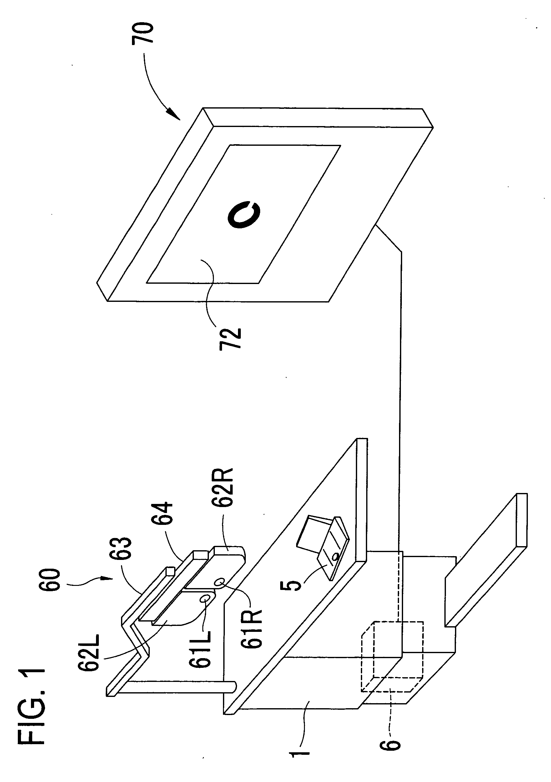
[0023]A detailed description of a preferred embodiment of the present invention will now be given referring to the accompanying drawings. FIG. 1 is a schematic external view of a subjective vision testing system of the embodiment of the present invention.

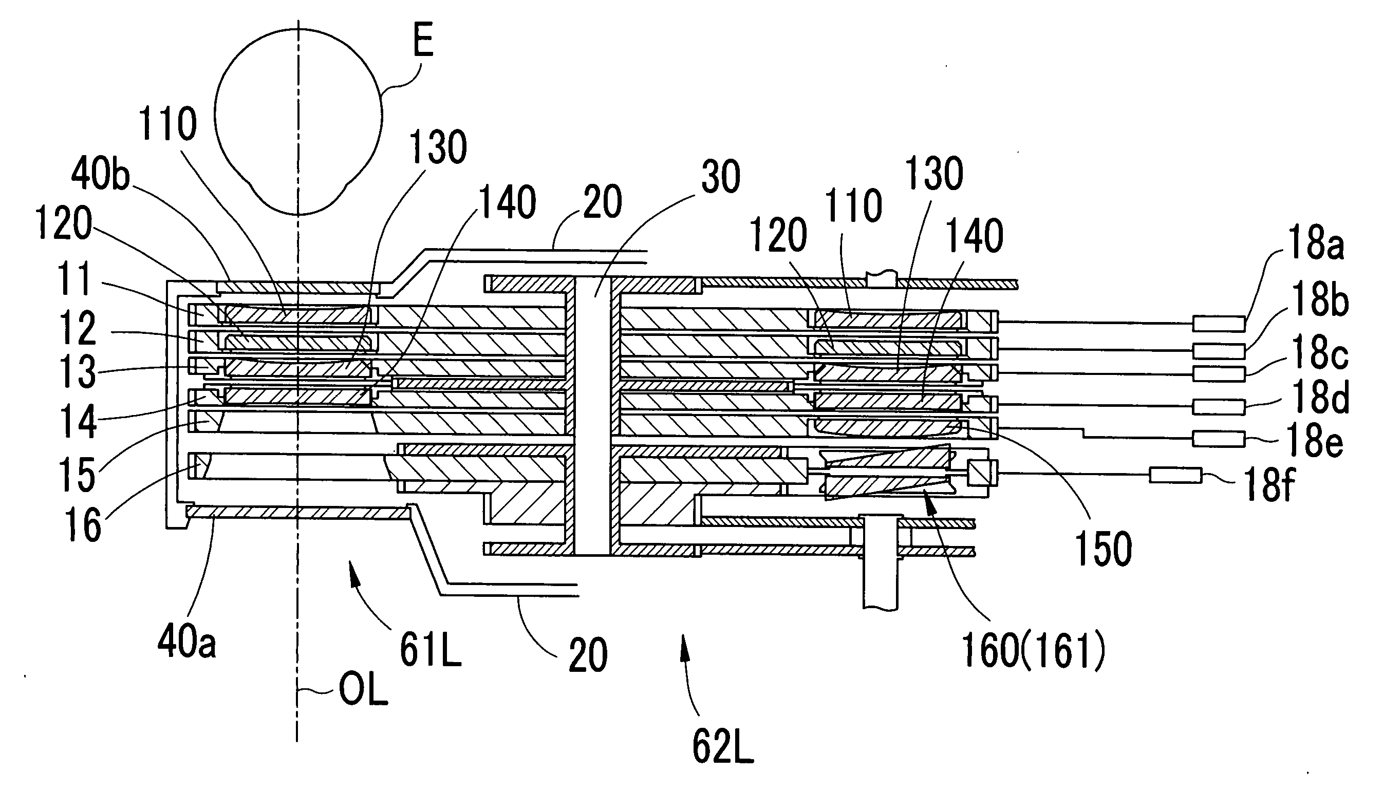
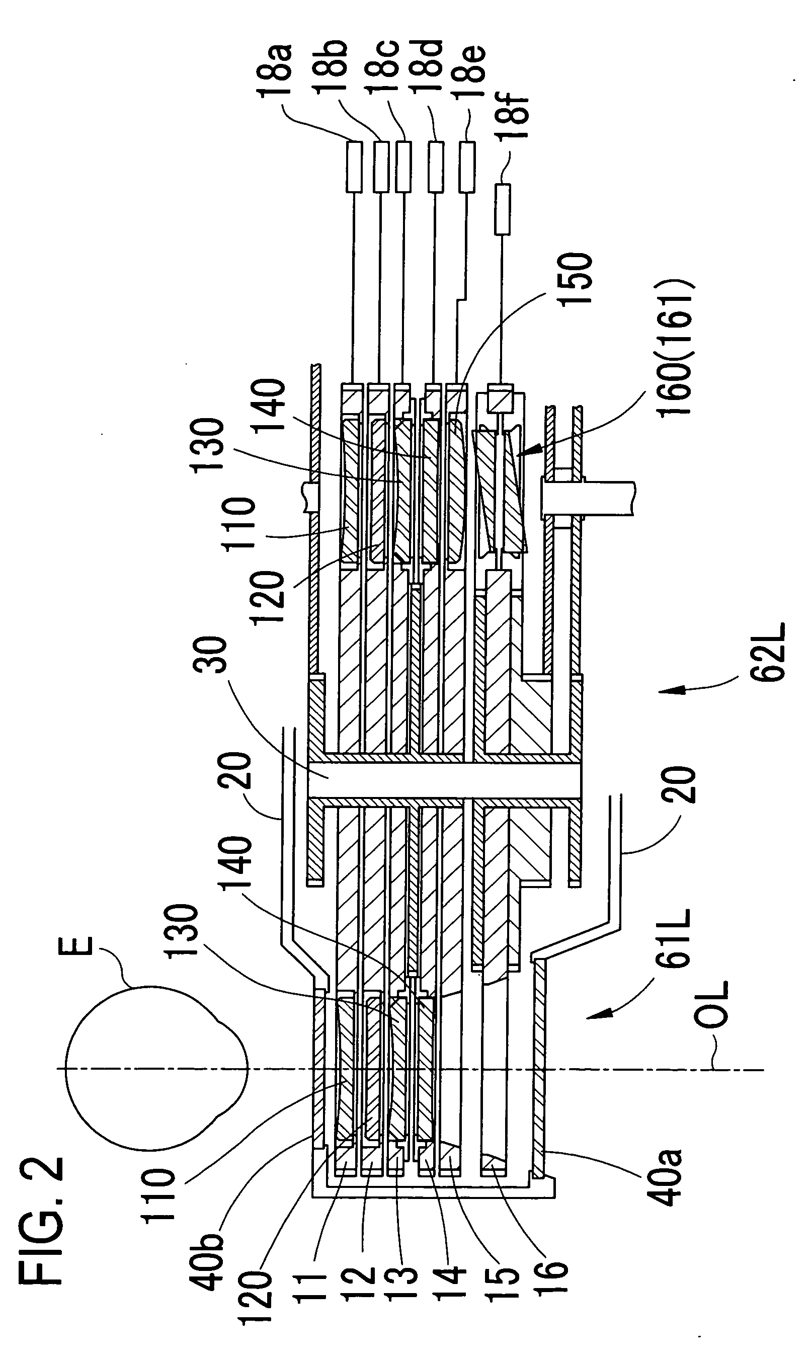
[0024]Above a table 1, an optometric apparatus 60, called a phoropter or a refractor, for subjectively testing visual functions of examinee's eyes is placed with an arm 63. The optometric apparatus 60 includes a pair of symmetric lens chamber units 62R and 62L, and a moving unit 64. The lens chamber unit 62R has a test window 61R and the lens chamber unit 62L has a test window 61L. In each inside of the lens chamber units 62R and 62L, lens disks 11 to 16 mentioned later and others are arranged. The lens chamber units 62R and 62L can be slid on the same line by the moving unit 64 provided thereon to change a distance therebetween. Furthermore, they are converged to change a convergence angle therebetween.

[0025]An optotype presenting ...


PUM


Abstract

A subjective vision testing system is used for visual function tests for examinees. The subjective vision testing system is provided with an optometric apparatus which selectively sets optical elements in front of both eyes of an examinee, an optotype presenting apparatus for displaying optotypes to the examinee, and a controller. The optotype presenting apparatus, based on a command signal for implementation of a binocular balance test, displays optotypes used for binocular balance tests. The optometric apparatus, based on a command signal for implementation of a binocular balance test, sets a first prism in front of the examinee's right eye and a second prism in front of the examinee's left eye. The second prism has a base direction vertically opposite to the first prism and the same prism power as the first prism.

Description

CROSS-REFERENCE TO RELATED APPLICATIONS[0001]This is a national phase application based on the PCT International Patent Application No. PCT / JP2007 / 058944 filed on Apr. 25, 2007, the entire contents of which are incorporated herein by reference.TECHNICAL FIELD[0002]The present invention relates to a subjective vision testing system for testing visual functions of examinee's eyes.BACKGROUND ART[0003]As an optotype presenting apparatus of a vision testing system, an apparatus arranged to present an optotype or chart on a color liquid crystal display (LCD) has recently been proposed as well as a conventional apparatus arranged to present an optotype on a screen by projection. Furthermore, an apparatus with the LCD for a binocular balance test has been proposed in which two LCDs placed one before the other and two polarization filters having polarization axes perpendicular to each other. In this apparatus, as with the conventional screen projection type apparatus, two polarization filter...

Claims


Application Information

Patent Timeline
IPC IPC(8): A61B3/08
CPCA61B3/0033A61B3/032A61B3/0285A61B3/02
Inventor HOSOI, YOSHINOBUKANAZAWA, YUICHIROTERABE, HIROHISAOZAKI, YOSHIHIRO
Owner NIDEK CO LTD
Why Eureka
Try Eureka