Vision Test Pattern Indicator

Active Publication Date: 2009-08-27
NIDEK CO LTD
View PDF6 Cites 2 Cited by
  • Summary
  • Abstract
  • Description
  • Claims
  • Application Information

AI Technical Summary

Benefits of technology

[0012]According to the vision test pattern indicator according to the inventi

Problems solved by technology

However, such configuration having two LCDs and two polarization filt

Method used


Image

  • Vision Test Pattern Indicator
  • Vision Test Pattern Indicator
  • Vision Test Pattern Indicator

Examples


Embodiment Construction

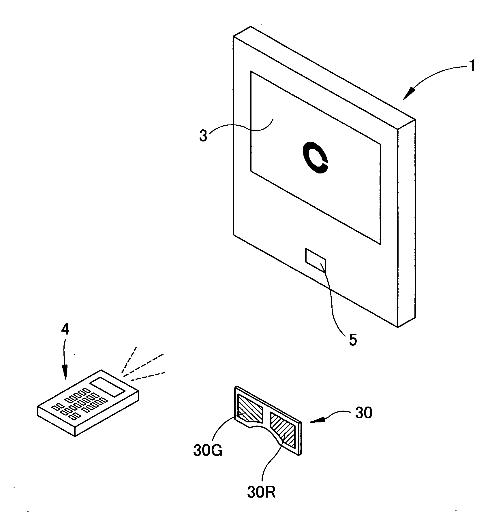
[0025]A detailed description of a preferred embodiment of the present invention will now be given referring to the accompanying drawings. FIG. 1 is a schematic configuration view of an optotype presenting apparatus in the embodiment of the present invention.

[0026]A main unit 1 of the optotype presenting apparatus includes a presenting part 3 constituted of a color liquid display. The main unit 1 also includes a receiving part 5 which receives a signal from a remote controller 4. An optotype to be centrally displayed on the presenting part 3 is changed by operation of the controller 4.

[0027]A red / green spectacles 30 used for a binocular vision test has a red filter 30R for right eye and a green filter 30G for left eye.

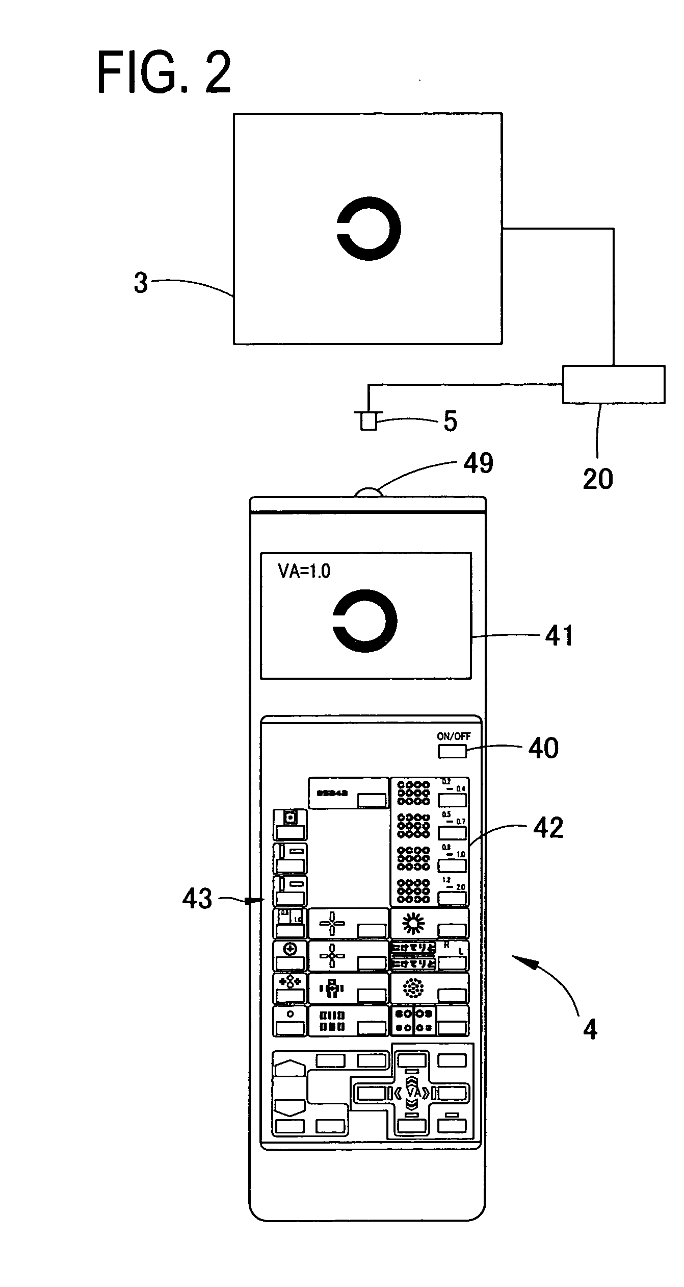
[0028]FIG. 2 is a schematic external view of the controller 4 and a schematic block diagram of a control system of the optotype presenting apparatus. An arithmetic control part 20 of the optotype presenting apparatus (the main unit 1) is connected to the presenting part...


PUM


Abstract

A vision test pattern indicator is provided with a color display for displaying optotypes used for binocular vision tests which are conducted with a red filter set in front of an eye of an examinee and a green filter set in front of the other eye, and an arithmetic control part which controls the color display as a first optotype figure is displayed in a green color, a second optotype figure is displayed in a red color, a third optotype figure for fusion stimulus is displayed in a color excluding red and green components and a background of the optotypes is displayed in a white color.

Description

CROSS-REFERENCE TO RELATED APPLICATIONS[0001]This is a national phase application based on the PCT International Patent Application No. PCT / JP2007 / 058725 filed on Apr. 23, 2007, the entire contents of which are incorporated herein by reference.TECHNICAL FIELD[0002]The present invention relates to a vision test pattern indicator (an optotype presenting apparatus) for presenting an optotype for testing visual functions of an examinee's eye.BACKGROUND ART[0003]As an optotype presenting apparatus, in addition to an apparatus of a conventional type arranged to project and present an optotype on a screen, an apparatus of another type arranged to present an optotype on a color liquid crystal display (LCD) has recently been proposed. One of apparatus using the LCD for binocular vision tests such as an aniseikonia test and a stereoscopic vision test has been proposed as an apparatus including two LCDs placed in tandem and two polarization filters having polarization axes perpendicular to eac...

Claims


Application Information

Patent Timeline
IPC IPC(8): A61B3/08
CPCA61B3/032A61B3/08A61B3/066A61B3/0325H04N13/327A61B3/02
Inventor HOSOI, YOSHINOBUKANAZAWA, YUICHIRO
Owner NIDEK CO LTD
Why Eureka
Try Eureka