Non-contact power transmission system
- Summary
- Abstract
- Description
- Claims
- Application Information
AI Technical Summary
Benefits of technology
Problems solved by technology
Method used
Image
Examples
first embodiment
1 First Embodiment
[1.1 Structure of Non-Contact Power Transmission System 10]
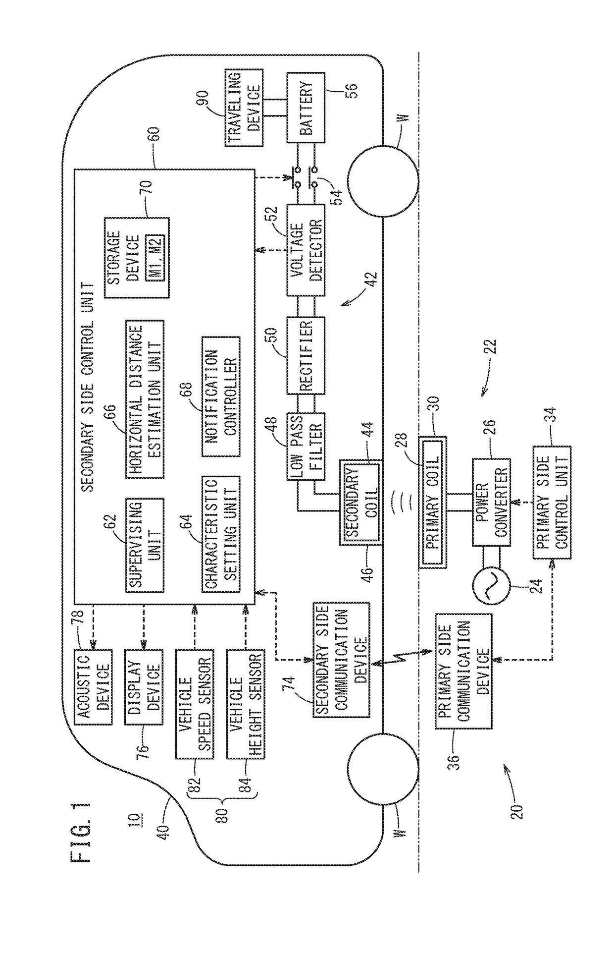
[0028]A structure of a non-contact power transmission system 10 according to a first embodiment will be described with reference to FIG. 1. The non-contact power transmission system 10 includes a charging station 20 on a primary side (power transmission side) that is provided on the ground (installation surface), and an electric vehicle 40 on a secondary side (power reception side). In FIG. 1, components below a two-dot chain line correspond to the charging station 20, and components above the two-dot chain line correspond to the electric vehicle 40. In the non-contact power transmission system 10, a battery 56 that is mounted on the electric vehicle 40 is charged by the charging station 20 without contact.
[0029]The charging station 20 mainly includes a power transmission circuit 22, a primary side control unit 34, and a primary side communication device 36. The power transmission circuit 22 includes an alt...
second embodiment
2 Second Embodiment
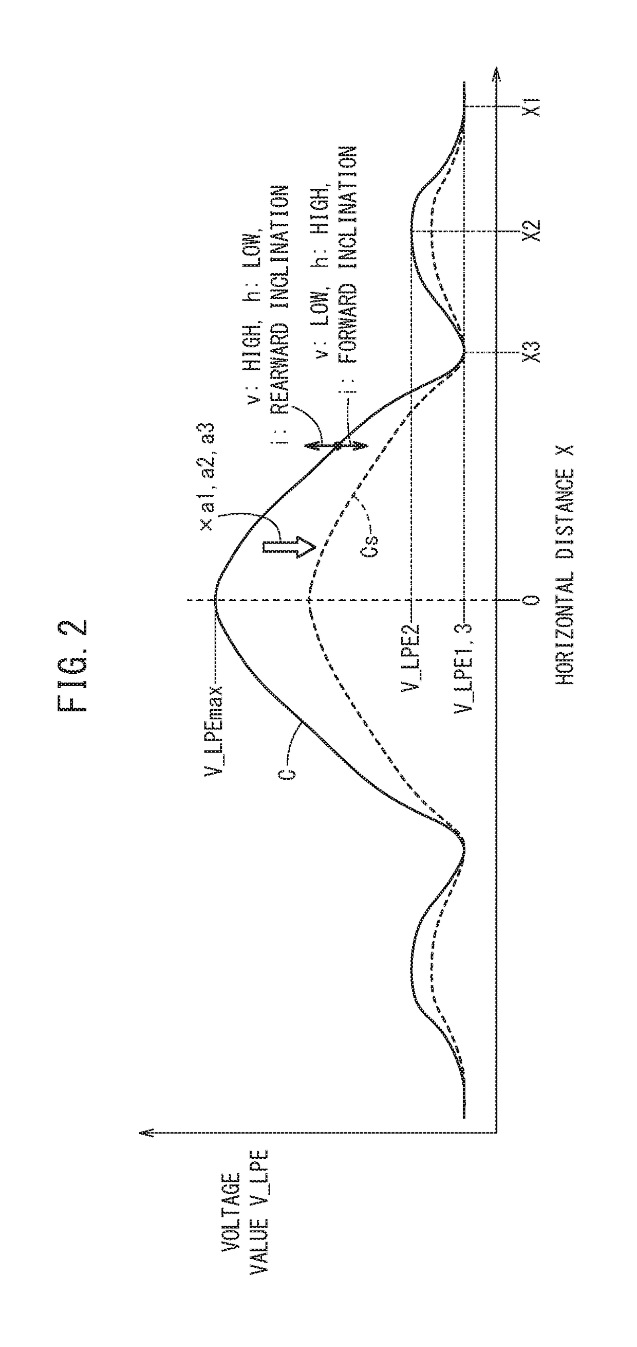
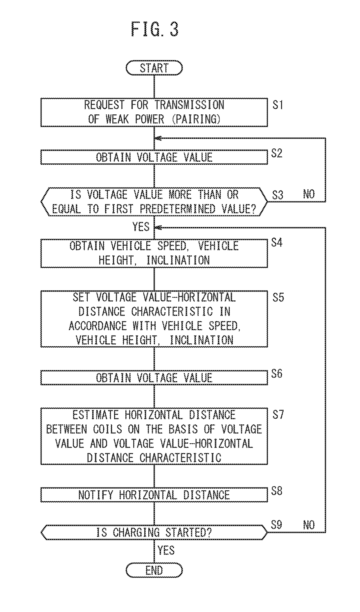
[0060]In the first embodiment, a referential voltage value-horizontal distance characteristic C is corrected, on the basis of the values detected by the sensors 80, to the voltage value-horizontal distance characteristic Cs that matches each vehicle state. As will be described in a second embodiment, however, each voltage value-horizontal distance characteristic Cs may be stored in advance, and the voltage value-horizontal distance characteristic Cs matching each vehicle state may be selected based on the values detected by the sensors 80.
[0061]In the second embodiment, the storage device 70 stores in advance, as the map M1, the voltage value-horizontal distance characteristics Cs matching the vehicle states. In the second embodiment, the voltage value-horizontal distance characteristics Cs are collectively defined as the voltage value-horizontal distance characteristic C. The characteristic setting unit 64 selects, from the voltage value-horizontal distance chara...
third embodiment
3 Third Embodiment
[3.1 Structure of Non-Contact Power Transmission System 10]
[0063]A structure of the non-contact power transmission system 10 according to a third embodiment is described with reference to FIG. 5. Elements that are the same as those of the first embodiment are given the same reference numerals without the repeated description thereof. The non-contact power transmission system 10 according to the third embodiment is different from the non-contact power transmission system 10 according to the first embodiment in that the non-contact power transmission system 10 according to the third embodiment includes a structure for adjusting the vehicle height h and the inclination i.
[0064]The secondary side control unit 60 also functions as a vehicle height controller 100 by the processor such as a CPU (not shown) reading out programs stored in the storage device 70 and executing the programs. The vehicle height controller 100 outputs an instruction signal to a suspension control...
PUM
 Abstract
Description
Claims
Application Information
 - R&D
- Intellectual Property
- Life Sciences
- Materials
- Tech Scout
- Unparalleled Data Quality
- Higher Quality Content
- 60% Fewer Hallucinations
Browse by: Latest US Patents, China's latest patents, Technical Efficacy Thesaurus, Application Domain, Technology Topic, Popular Technical Reports.
© 2025 PatSnap. All rights reserved.Legal|Privacy policy|Modern Slavery Act Transparency Statement|Sitemap|About US| Contact US: help@patsnap.com


