Cam mechanism of a retractable zoom lens

Inactive Publication Date: 2009-08-06
HOYA CORP
View PDF10 Cites 2 Cited by
  • Summary
  • Abstract
  • Description
  • Claims
  • Application Information

AI Technical Summary

Benefits of technology

[0008]The present invention provides a cam mechanism of a retractable zoom lens using a cam ring which is structured so as to strike a balance between ease of accuracy control of each cam groove and the associated cam follower of the cam mechanism and accurate guiding performance, while achieving a reduction in length of the cam ring in an opt

Problems solved by technology

It is generally the case that it is more difficult to control the overall accuracy of the cam mechanism as the number of cam grooves and associated cam followers increases

Method used


Image

  • Cam mechanism of a retractable zoom lens
  • Cam mechanism of a retractable zoom lens
  • Cam mechanism of a retractable zoom lens

Examples


Example

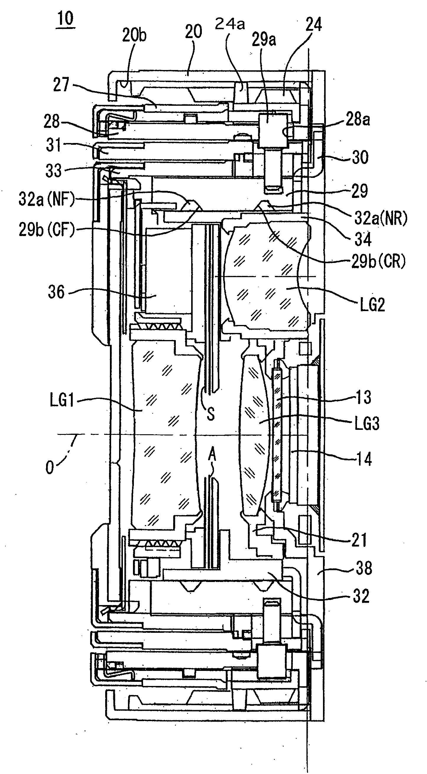
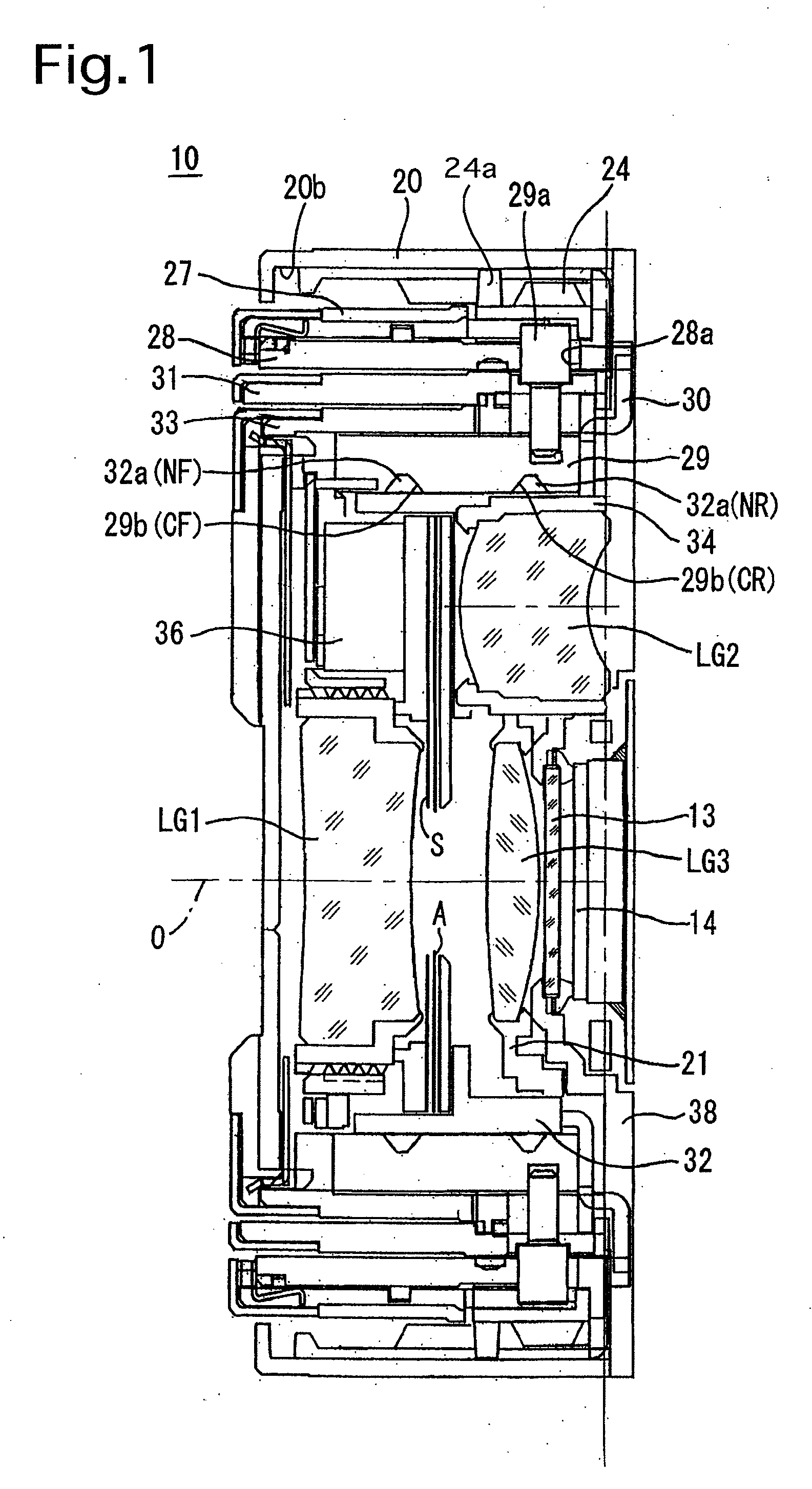
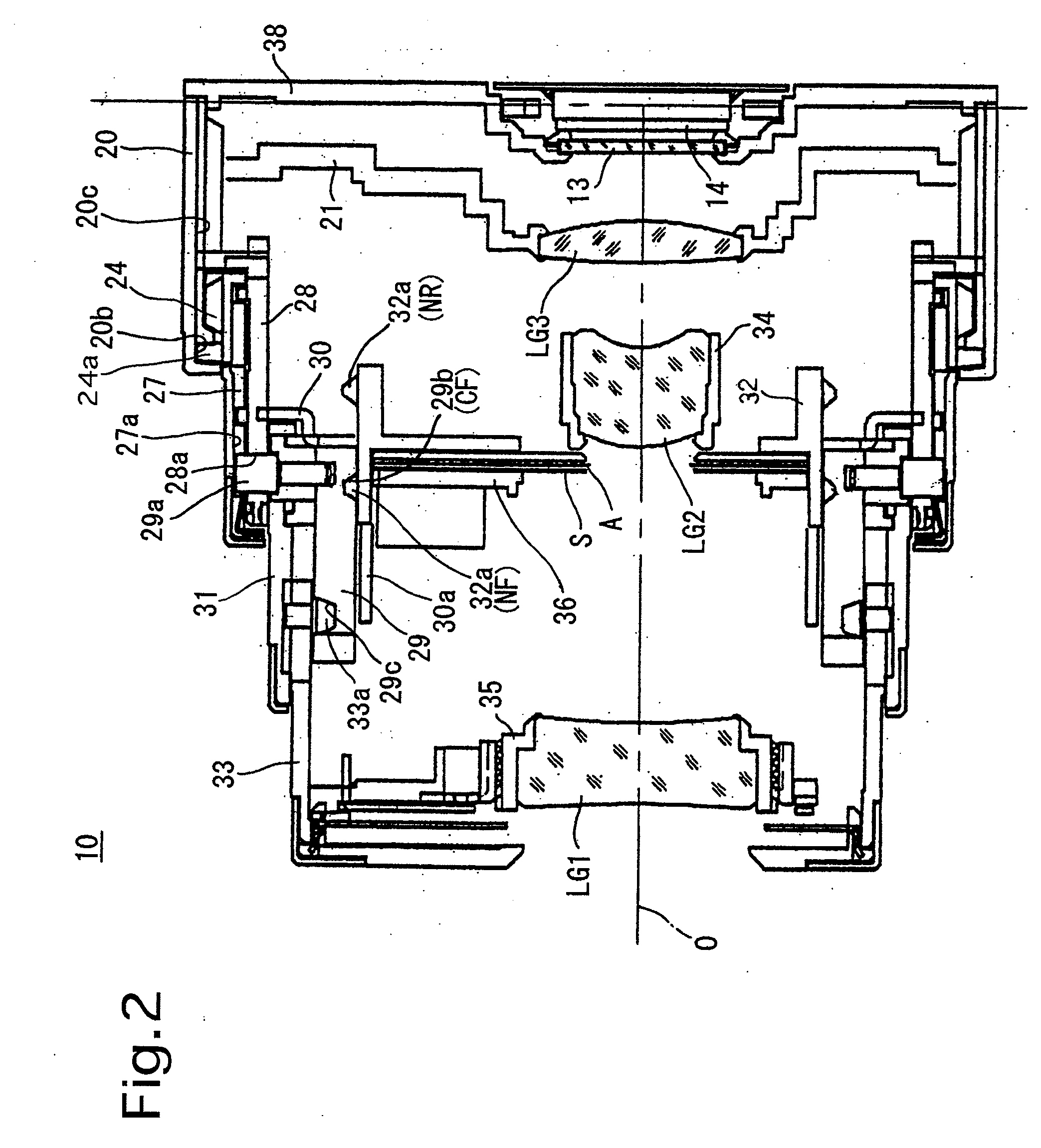
[0040]FIGS. 1 through 3 show cross sectional views of an embodiment (first embodiment) of a retractable type of zoom lens (zoom lens barrel) 10 having a cam mechanism according to the present invention. FIG. 1 shows the lens barrel accommodated state (retracted state) of the zoom lens 10, in which no pictures are taken, FIG. 2 shows the zoom lens 10 set at the wide-angle extremity, and FIG. 3 shows the zoom lens 10 set at the telephoto extremity. The zoom lens 10 is constructed so that a CCD image sensor unit supported by a CCD holder 38 is mounted to the back of a lens group unit supported by a housing 20 of the zoom lens 10.

[0041]A photographing optical system of the zoom lens 10 includes a first lens group LG1, a shutter S, an adjustable diaphragm A, a second lens group LG2, a third lens group LG3, a low-pass filter (optical filter) 13, and a CCD image sensor (image pickup device) 14. This photographing optical system is a zoom optical system (zoom optical system) in which the fo...

Example

[0083]The second embodiment of the zoom lens is provided with a lens moving frame (driven member) 42 shown in FIG. 13 which holds a lens group (not shown), and six cam followers 43 which are respectively engaged in the six cam grooves 41 are formed on an outer peripheral surface of the lens moving frame 42. Similar to the six cam followers 32a in the first embodiment of the zoom lens 10, the six cam followers 43 include two types of cam followers: a set of three front cam followers 43F that are formed at different circumferential positions, and a set of three rear cam followers 43R that are formed at different circumferential positions behind the set of three front cam followers 43F in the optical axis direction. The lens moving frame 42 is provided with three linear guide grooves 44 each having a pair of parallel guide surfaces parallel to an optical axis (not shown) of the zoom lens. The second embodiment of the zoom lens is provided with a linear guide ring 45 shown in FIG. 13 ha...


PUM


Abstract

A cam mechanism includes a cam ring having front and rear cam grooves which have a common reference cam diagram and are formed so that a front part of the front cam groove and a rear part of the rear cam groove are omitted from the reference cam diagram. A normal-width section and a wide-width section are provided in each of the front and rear cam grooves. In a zoom range, an associated cam follower of a driven member is engaged in the normal-width section of one of the front and rear cam grooves, and another associated cam follower of the driven member is positioned out of the other of the front and rear cam grooves. In a transition state between the zoom range and an accommodated position, both of the associated cam followers are positioned out of the normal-width sections of the respective front and rear cam grooves.

Description

BACKGROUND OF THE INVENTION[0001]1. Field of the Invention[0002]The present invention relates to a cam mechanism which is incorporated in a retractable zoom lens (lens barrel).[0003]2. Description of the Related Art[0004]The assignee of the present invention has proposed an advancing / retracting movement guide mechanism in U.S. Pat. No. 7,039,308, wherein the advancing / retracting movement guide mechanism has a structure making it possible to achieve a reduction in length of a cam ring in an optical axis direction without sacrificing the range of movement of each lens group or the like provided as a driven member in a lens barrel. This cam mechanism is characterized in that a plurality of cam grooves which trace substantially the same reference cam diagram are formed on the cam ring at different positions at least in the optical axis direction, that all cam grooves of the plurality of cam grooves are formed as partial cam grooves each having at least one end opening at least one of th...

Claims


Application Information

Patent Timeline
IPC IPC(8): G02B7/10G02B7/04
CPCG03B17/12G03B17/04
Inventor ISHIZUKA, KAZUNORISUZUKI, TOSHIHARUOISHI, MAKIOMIYA, KOTA
Owner HOYA CORP
Why Eureka
Try Eureka