
Robot hand

Inactive Publication Date: 2021-07-01
NAVER LABS CORP +1
View PDF0 Cites 2 Cited by
  • Summary
  • Abstract
  • Description
  • Claims
  • Application Information

AI Technical Summary

Benefits of technology

The robot hand has multiple finger modules, each with its own drive unit that allows for independent movement. The thumb is also rotatable, allowing for natural motion and accurate object manipulation. The finger module design reduces the number of required parts, making manufacturing easier and less expensive. The finger module is quickly restored to its original state and has elastic members to control its posture, allowing for precise control. Overall, the robot hand has improved manipulation capabilities and is easier to control and manufacture.

Problems solved by technology

However, the driving method as described above has excellent power transmission and high durability but has a disadvantage of occupying a large space and increasing the size and weight of the robot hand.
However, there may be a problem in that the wire may be loosened when the joint is operated, and precise control may not be possible depending on shapes of joints and methods of implementing wires.
However, even in the case of Patent Documents 1 and 2, a motor is attached to each joint of the finger, which causes an increase in size and weight of the robot hand.
Further, simple operations such as an operation of picking up an object and an operation of throwing an object may be performed, but the precise operation required by a surgical robot or an artificial arm cannot be performed.
In addition, because members such as dampers and springs have repulsive properties, it is difficult to estimate the exact position of the finger, and an additional sensor such as a deflection measurement sensor is required to estimate the position.

Method used


Image

  • Robot hand
  • Robot hand
  • Robot hand

Examples


Embodiment Construction

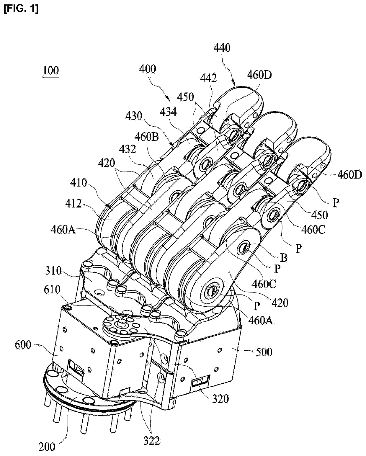
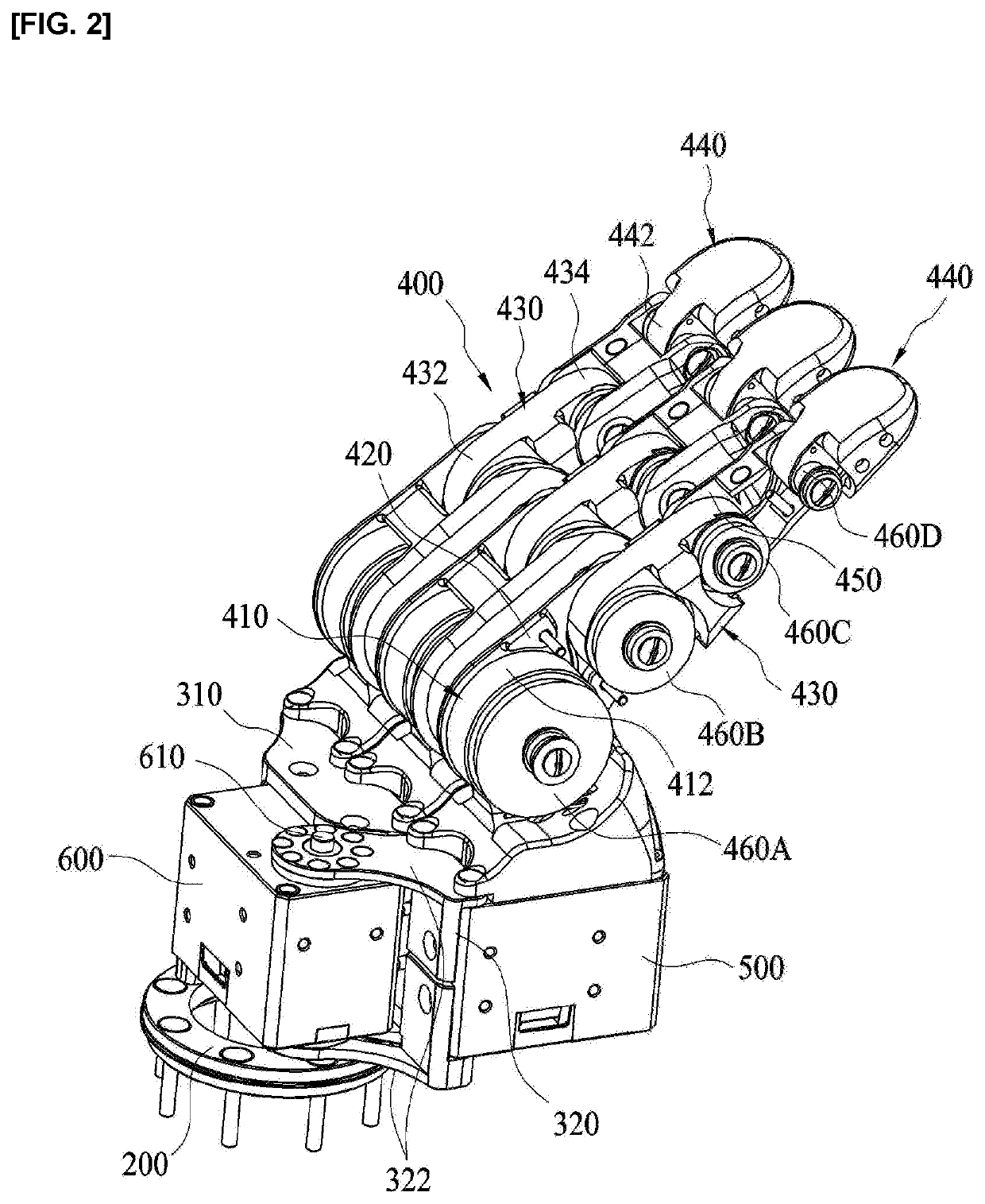
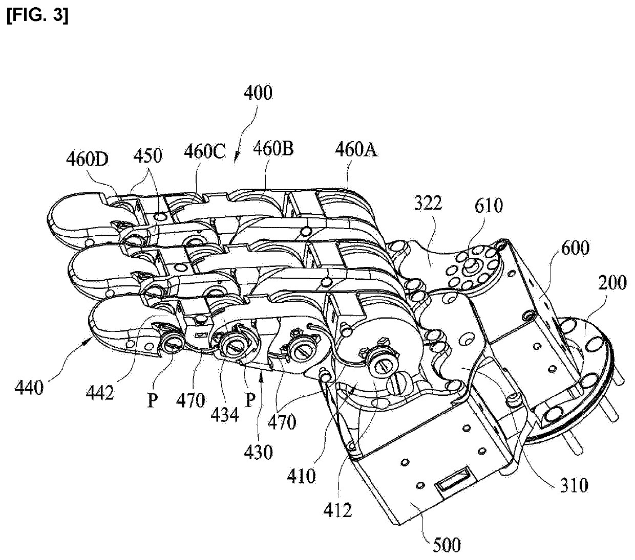
[0030]In the exemplary embodiment of the present invention, a robot hand comprises a base, a first bracket provided on an upper portion of the base, a second bracket provided on an upper portion of the base and configured such that the other side of the second bracket is rotatable in a horizontal direction about one side of the second bracket, a plurality of finger modules coupled to upper portions of the first and second brackets, respectively, and configured to tilt in order to grip an object, finger drive units installed on the first and second brackets and configured to transmit driving power to the finger modules, and a rotation drive unit installed at one side of the second bracket and configured to transmit driving power so that the other side of the second bracket is rotatable in the horizontal direction about one side of the second bracket.

[0031]Hereinafter, the exemplary embodiments of the present invention will be described in detail with reference to the accompanying dra...


PUM


Abstract

Disclosed is a robot hand comprising a base, a first bracket provided on an upper portion of the base, a second bracket provided on an upper portion of the base and configured such that the other side of the second bracket is rotatable in a horizontal direction about one side of the second bracket, a plurality of finger modules coupled to upper portions of the first and second brackets, respectively, and configured to tilt in order to grip an object, finger drive units installed on the first and second brackets and configured to transmit driving power to the finger modules and a rotation drive unit installed at one side of the second bracket and configured to transmit driving power so that the other side of the second bracket is rotatable in the horizontal direction about one side of the second bracket.

Description

TECHNICAL FIELD[0001]The present invention relates to a robot hand, and more particularly, to a robot hand capable of being precisely controlled and accurately performing an operation corresponding to a shape of an object.BACKGROUND ART[0002]Recently, studies on humanoid robots (android or humanoid) have been actively conducted. In order for such a humanoid robot to perform a task performed by a human hand, a robot hand capable of implementing a natural motion function is required.[0003]In general, the robot hand has finger assemblies, and a plurality of joints constituting each of the finger assemblies are all operated by motors. That is, the motors are directly attached to the joints, respectively, and the fingers are operated by the motors operating the joints.[0004]However, the driving method as described above has excellent power transmission and high durability but has a disadvantage of occupying a large space and increasing the size and weight of the robot hand.[0005]In order...

Claims


Application Information

Patent Timeline
IPC IPC(8): B25J15/10
CPCB25J15/10B25J15/0009B25J9/104B25J15/08B25J9/126B25J15/0233
Inventor KIM, YONG JAEKIM, JONG INYOON, JUN SUK
Owner NAVER LABS CORP
Learn More