Shake detection device and shake correction device of imaging device, imaging device, and shake detection method
Active Publication Date: 2019-08-22
FUJIFILM CORP
View PDF0 Cites 2 Cited by
Summary
Abstract
Description
Claims
Application Information
AI Technical Summary
This helps you quickly interpret patents by identifying the three key elements:
Problems solved by technology
Method used
Benefits of technology
Benefits of technology
The present invention provides a shake detection and correction device for an imaging device that can accurately determine the shift amount of the reference value of the shake detection sensor even when the imaging device is in a hand-held state. This enables high-accuracy shake detection and correction to be performed. Additionally, the invention includes a method to extract low and high frequency components from the output of the shake detection sensor to determine if the imaging device is in a hand-held state or a fixed-point imaging state and to accurately calculate the reference value shift amount. The invention thus enables accurate shake detection and correction to be performed even in situations where the reference value may be changing due to drift.
Problems solved by technology
For example, since the panning detection unit described in JP2013-178503A detects panning based on a change amount of the direct current component of the sensor output of the gyro sensor with time, it is possible to detect panning in which the angular velocity is gradually increased, but it is not possible to detect typical panning in which the angular velocity is constant.
Since the direct current component of the sensor output before the reference value is subtracted is used for detecting panning, it is not possible to determine whether the sensor output is drifted or a panning operation at a very low speed is performed.
Accordingly, since the reference value of the gyro sensor is erroneously detected, there is a problem that shake detection accuracy (shake correction accuracy) deteriorates.
In the panning determination method described in JP2002-359768A, since a direct current drift component of an unnecessary band component included in the sensor output is removed from the sensor output of the angular velocity sensor by using the high-pass filter and the panning is determined based on the sensor output after the direct current drift component is removed, it is not possible to determine the panning at the very low speed corresponding to the drift.
Method used
Image
Click on the blue label to locate the original text in one second.
Reading with bidirectional positioning of images and text.
Examples
first embodiment
[0101]Next, the shake detection device according to the embodiment of the present invention will be described.
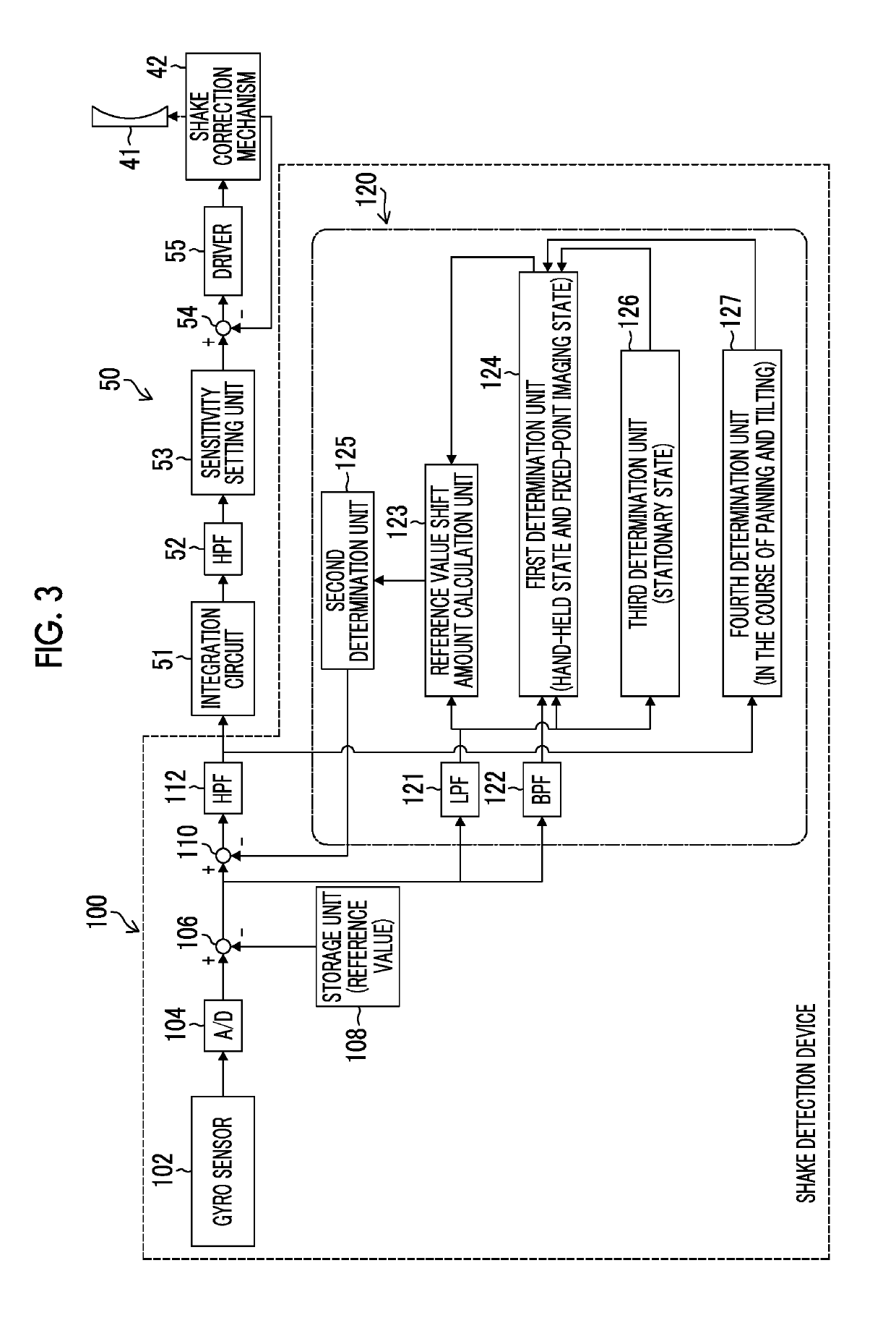
[0102]The shake correction device shown in FIG. 3 includes the shake detection device 100 of the first embodiment.
[0103]The shake detection device 100 mainly includes the gyro sensor 102 functioning as a shake detection sensor, an A / D converter 104, subtraction units 106 and 110, a storage unit 108, an HPF 112 functioning as a third filter, and a reference value correction unit 120.
[0104]Although the gyro sensor 102 detects the angular velocities of the two axes (yaw and pitch) of the imaging device 1 and outputs the analog angular velocity signals indicating the detected angular velocities, it is assumed in FIG. 3 that the angular velocity signal of one axis of the yaw or the pitch is output as stated above for simplicity of description.
[0105]The angular velocity signal output from the gyro sensor 102 is converted into the digital angular velocity signal by the A / D converte...
second embodiment
[0157]Next, the shake detection device according to the embodiment of the present invention will be described.
[0158]A shake correction device shown in FIG. 8 includes a shake detection device 100A of the second embodiment. In FIG. 8, portions in common with those in the shake detection device 100 of the first embodiment shown in FIG. 3 will be assigned the same references, and the detailed description thereof will be omitted.
[0159]In the shake detection device 100A of the second embodiment shown in FIG. 8, a reference value correction unit 120A is different from the reference value correction unit 120 of the shake detection device 100 of the first embodiment. Particularly, the reference value correction unit 120A is different from the reference value correction unit 120 of the shake detection device 100 of the first embodiment in that a temperature sensor 128 is added and the determination content of a second determination unit 125A is different.
[0160]The temperature sensor 128 dete...
third embodiment
[0170]Next, the shake detection device according to the embodiment of the present invention will be described.
[0171]The shake correction device shown in FIG. 10 includes a shake detection device 100B of the third embodiment. In FIG. 10, portions in common with those in the shake detection device 100A of the second embodiment shown in FIG. 8 will be assigned the same references, and the detailed description thereof will be omitted.
[0172]In the shake detection device 100B of the third embodiment shown in FIG. 10, a reference value correction unit 120B is different from the reference value correction unit 120A of the second embodiment and an HPF 112A and a second determination unit 125B are particularly different from the HPF 112 and the second determination unit 125A of the shake detection device 100A of the second embodiment.
[0173]The second determination unit 125B has the same function as that of the second determination unit 125A of the shake detection device 100A of the second emb...
PUM
Abstract
There are provided a shake detection device of an imaging device, a shake correction device, an imaging device, and a shake detection method which are capable of performing high-accurate shake detection and shake correction. A shake detection device subtracts a reference value from a sensor output of a gyro sensor, and extracts a low frequency component and a high frequency component from a sensor output after the reference value subtraction by using an LPF and a BPF. A first determination unit determines whether or not the imaging device is in a fixed-point imaging state based on the LPF output and the BPF output. In a case where it is determined that the imaging device is in the fixed-point imaging state, a reference value shift amount calculation unit calculates a shift amount (reference value shift amount) for the reference value based on the LPF output for a period during which the determination is performed. A subtraction unit corrects the reference value by subtracting the reference value shift amount from the sensor output after the reference value subtraction. An HPF removes a low frequencynoise from the sensor output after the correction of the reference value shift amount. High-accurate shake is detected.
Description
CROSS-REFERENCE TO RELATED APPLICATIONS[0001]The present application is a Continuation of PCT International Application No. PCT / JP2017 / 029777 filed on Aug. 21, 2017 claiming priority under 35 U.S.C. § 119(a) to Japanese Patent Application No. 2016-180811 filed on Sep. 15, 2016. Each of the above applications is hereby expressly incorporated by reference, in their entirety, into the present application.BACKGROUND OF THE INVENTION1. Field of the Invention[0002]The present invention relates to a shake detection device and a shake correction device of an imaging device, an imaging device, and a shake detection method, and particularly, to a technology capable of performing high-accurate shake detection and shake correction.2. Description of the Related Art[0003]In the related art, a gyro sensor is used for detecting shake (angular velocity) of a camera required for correcting the shake of the camera. Since a reference value (an output at the time of stationary) as an output of the gyro ...
Claims
Application Information
Patent Timeline
Application Date:The date an application was filed.
Publication Date:The date a patent or application was officially published.
First Publication Date:The earliest publication date of a patent with the same application number.
Issue Date:Publication date of the patent grant document.
PCT Entry Date:The Entry date of PCT National Phase.
Estimated Expiry Date:The statutory expiry date of a patent right according to the Patent Law, and it is the longest term of protection that the patent right can achieve without the termination of the patent right due to other reasons(Term extension factor has been taken into account ).
Invalid Date:Actual expiry date is based on effective date or publication date of legal transaction data of invalid patent.

