Broaching Tool

a tool and tooling technology, applied in the field of machine tooling, can solve the problems of easy yield of inferior parts, easy dulling of cutting formed by the bit or insert, and slow process, and achieve the effect of reducing chatter

Active Publication Date: 2009-12-03
GARDNER LARRY JOHN
View PDF14 Cites 3 Cited by
  • Summary
  • Abstract
  • Description
  • Claims
  • Application Information

AI Technical Summary

Benefits of technology

[0025]From the planar center section of both sidewalls, a relief is formed in the sidewall surface, to angle it toward the first and second side surfaces. This relief is substantially triangular in shape to thereby keep the planar center sections of both sidewalls running parallel to the center axis of the body when in the as-used position.
[0026]It is thus an object of the invention to provide a machine tool for broaching which provides a cutting insert engaged to a ...

Problems solved by technology

Over time, the cutting formed by the bit or insert tends to dull from repeated contact with the workpiece to remove material.
A dull tool insert will not only slow the process, it can easily yield inferior parts from chatter and other problems inherent to contact of a dull insert with the workpiece being machined.
This is because the workpiece need not be removed and remounted from machine to machine, which causes errors in the accuracy of sequential cuts to the workpiece.
However, the temporary engagement with the holder using screws or other means of engagement suffers from chatter during machining of the workpiece due to the minimal contact of set screws and the like with the tool insert to engage it to the holder.
Additionally, such tool inserts generally require a new setup of th...

Method used


Image

  • Broaching Tool
  • Broaching Tool
  • Broaching Tool

Examples


Embodiment Construction

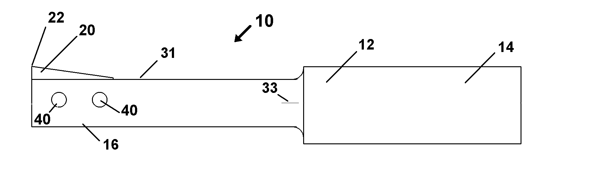
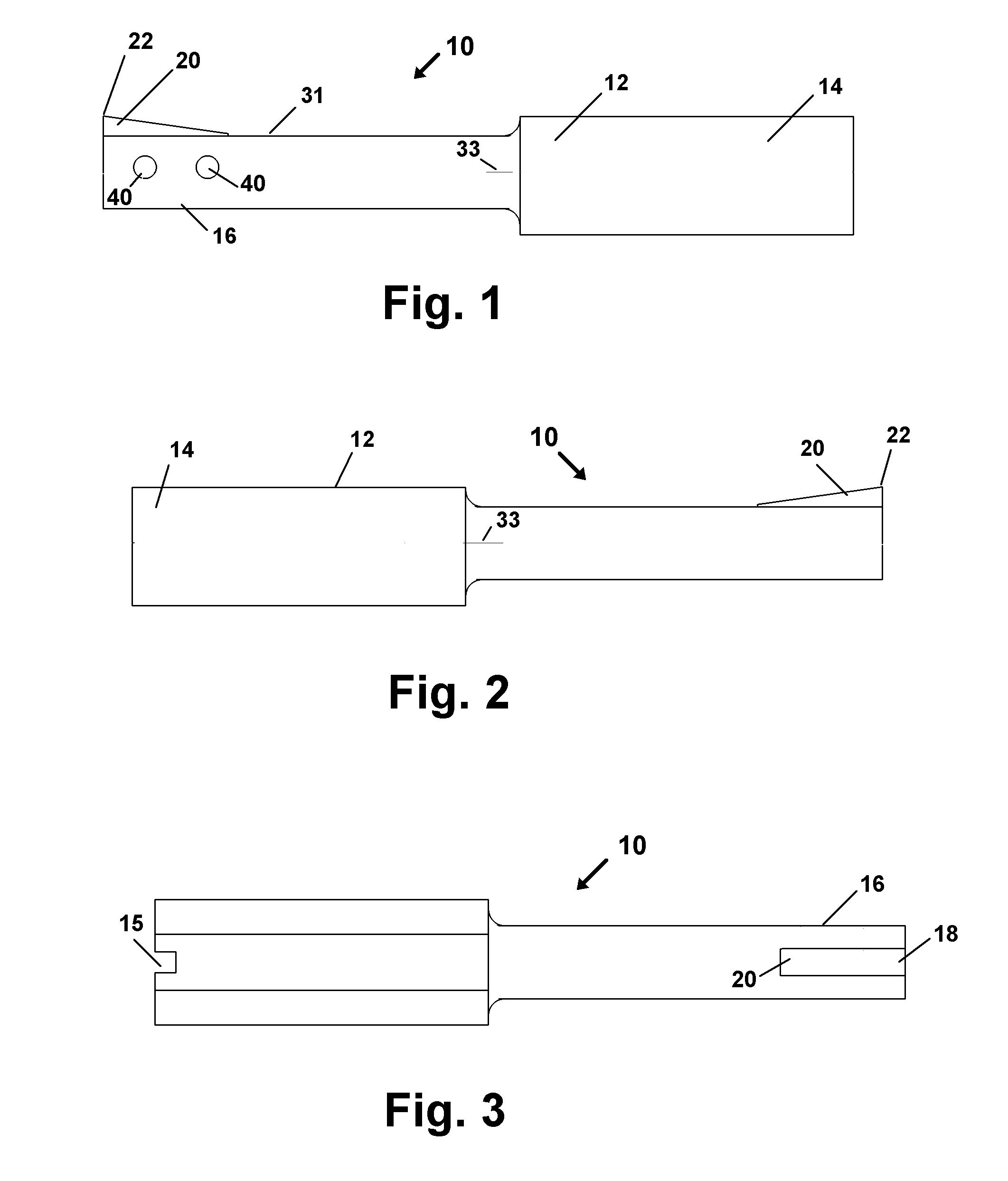
[0038]Referring now to the drawings in FIGS. 1-8 individually or as a group, wherein similar parts are identified by like reference numerals, the device 10 is depicted in figures as a broaching tool for cutting a workpiece.

[0039]A body 12 portion is adapted at a first end 14, for engagement to a machine tool mount on a lathe which would hold the workpiece. Also shown at the first end, 14 in FIG. 3 is a relief 15 which provides means for engagement of a cooling fluid for lubricating and cooling the workpiece and the insert 20 engaged in the slot 18 at the distal end 16 of the body 12.

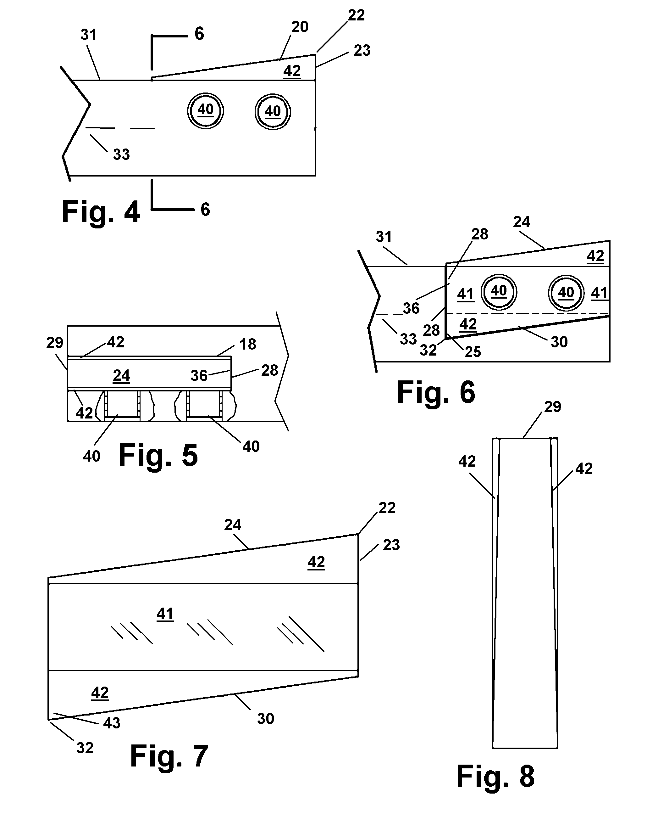
[0040]At the distal end 16 opposite the first end 14, the slot 18 is formed to provide means for registered engagement of a cutting insert 20 therein and contacting surfaces of the slot 18. The current preferred shape of the insert 20 is that of a parallelogram and the shape of the slot 18 is a conforming parallelogram.

[0041]The insert 20 has an as-used position shown in FIGS. 1, and 4-6 which depict it ...


PUM

PropertyMeasurementUnit
Widthaaaaaaaaaa
Distanceaaaaaaaaaa

Abstract

A broaching tool for machining a workpiece formed of a parallelogram shaped insert which fits within a slot formed in a body member. The insert has two juxtaposed corners either of which may be oriented at the distal end of the body member to function as a cutting edge. Repositioning of the insert to place either cutting edge in place is provided by flipping it over in its engagement within the slot. The inserts may be provided in a kit of differently configured inserts to yield different cutting widths.

Description

[0001]This application claims priority to U.S. Provisional Patent Application No. 61 / 130,427 filed on May 30, 2008 incorporated herein in it's entirety by reference.FIELD OF THE INVENTION[0002]The disclosed invention relates to machine tooling. More particularly it relates to a broaching tool having a reversible indexable cutting insert which is configured to maintain a registration with the engaged tool body when the insert is reversed to expose a new cutting edge of the insert.BACKGROUND OF THE INVENTION[0003]In the metalworking industry of machine shops, a cutting tool is any tool that is employed to remove metal from the workpiece being machined. This removal is accomplished generally by means of a shear deformation. Essentially, with the workpiece or the tool in motion, the tool is placed in controlled contact with the workpiece to thereby remove material such as metal strategically, to thereby form the desired shape to the workpiece.[0004]Tools generally employ a bit or insert...

Claims


Application Information

Patent Timeline
IPC IPC(8): B23D43/04
CPCB23B27/1603B23B29/04B23B2200/0447B23D13/00Y10T407/23Y10T409/501476Y10T409/509348Y10T407/1628Y10T407/1657Y10T409/502624
Inventor GARDNER, JAMES JOSEPH
Owner GARDNER LARRY JOHN
Why Eureka
Try Eureka