Internal combustion engine having an engine brake device

a technology of internal combustion engine and brake device, which is applied in the direction of machines/engines, non-mechanical valves, valve arrangements, etc., can solve the problems of time-consuming and costly regular manual adjustment, which is also susceptible to error, and becomes unnecessary, and achieves the effect of increasing the stability of the valve bridge and low overall height of the third piston/cylinder uni

Active Publication Date: 2012-07-24
MAN TRUCK & BUS AG
View PDF55 Cites 36 Cited by
  • Summary
  • Abstract
  • Description
  • Claims
  • Application Information

AI Technical Summary

Benefits of technology

[0014]The inventive internal combustion engine thus has not only the valve auxiliary control unit that is expedient for the engine braking force effect, but also a compensation mechanism, which automatically carries out the valve play adjustment. A time consuming and costly regular manual adjustment, which is also susceptible to error, becomes unnecessary. Thus, compared with previously known internal combustion engines that are equipped with an engine brake device, the inventive internal combustion engine offers an auxiliary functionality that makes the assembly and operation more reliable and efficient. Due to the automatic valve play adjustment, in particular the chattering of the exhaust valve is minimized, and damage to the valve drive due to a valve play that is set too small is prevented. Furthermore, due to the automatic valve play compensation during operation of the internal combustion engine, no valve play has to be bridged, so that the control times of the exhaust valve can be maintained exactly, resulting in an optimization of the exhaust gas or emission conditions of the internal combustion engine.
[0026]An embodiment where a piston of the third piston / cylinder unit is integrally formed with the piston of the first piston / cylinder unit is particularly space saving. Preferably, the first, the second and the third piston / cylinder units are integrally formed. The piston of the second piston / cylinder unit is, for example, guided in the valve bridge, whereby the piston of the first piston / cylinder unit is disposed and guided therein or in an auxiliary part disposed in the valve bridge. The piston of the third piston / cylinder unit is in turn arranged and guided in the piston of the first piston / cylinder unit. A low overall height of the valve bridge can be achieved with such a stacking of the piston / cylinder units. By means of a suitable dimensioning of the third piston / cylinder unit, slight control leakage quantities and hence slight jump lengths of the piston of the third piston / cylinder unit can be achieved. As a result, a low overall height of the third piston / cylinder unit is possible.

Problems solved by technology

A time consuming and costly regular manual adjustment, which is also susceptible to error, becomes unnecessary.

Method used


Image

  • Internal combustion engine having an engine brake device
  • Internal combustion engine having an engine brake device
  • Internal combustion engine having an engine brake device

Examples


first embodiment

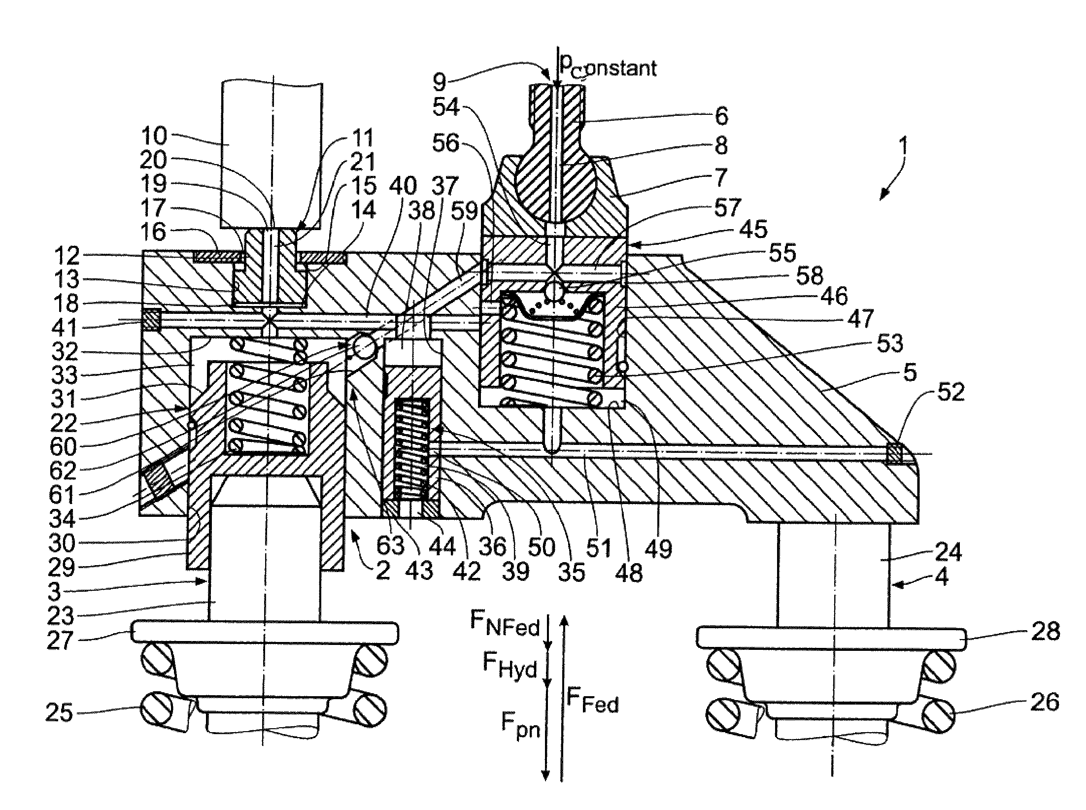
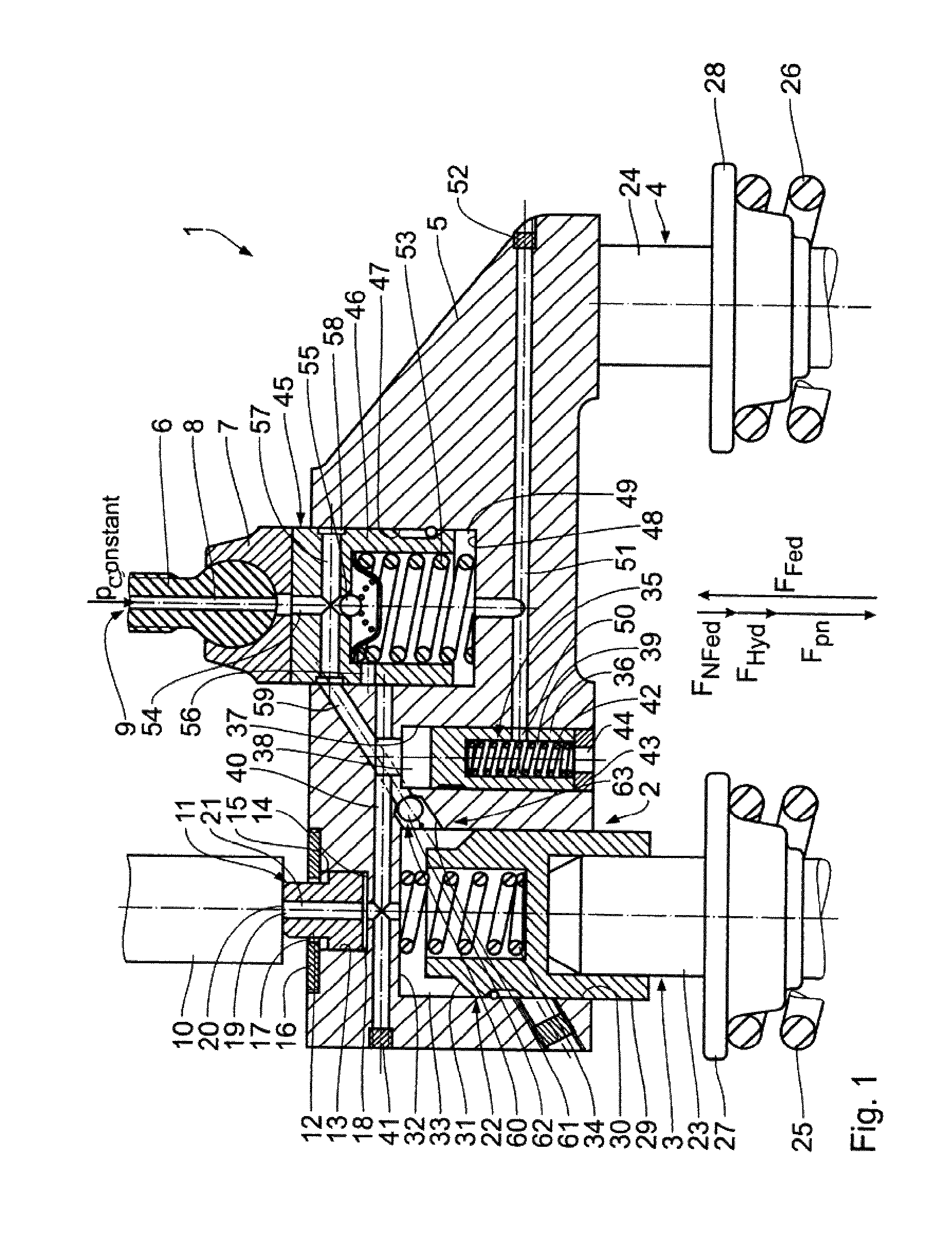
[0028]Referring now to the drawings in detail, the invention is described subsequently with the aid of FIG. 1. An internal combustion engine 1 having an engine brake device 2 is provided with a plurality of cylinders, which are not shown in FIG. 1 and which each delimit a combustion chamber. Air or an air / fuel mixture can be supplied to each of these combustion chambers by means of at least one intake valve. Furthermore, each combustion chamber has two exhaust valves 3 and 4, by means of which the exhaust gas can be withdrawn from the combustion chamber into the exhaust gas channel. The exhaust valves 3 and 4 can be mechanically controlled and operated by means of a common valve bridge 5. The valve bridge 5 is part of a connection mechanism that connects the exhaust valves 3 and 4 with a camshaft of the internal combustion engine 1, which is not illustrated in FIG. 1. The connection mechanism also includes a pivotably mounted rocker arm, which is also not illustrated in FIG. 1. By m...

second embodiment

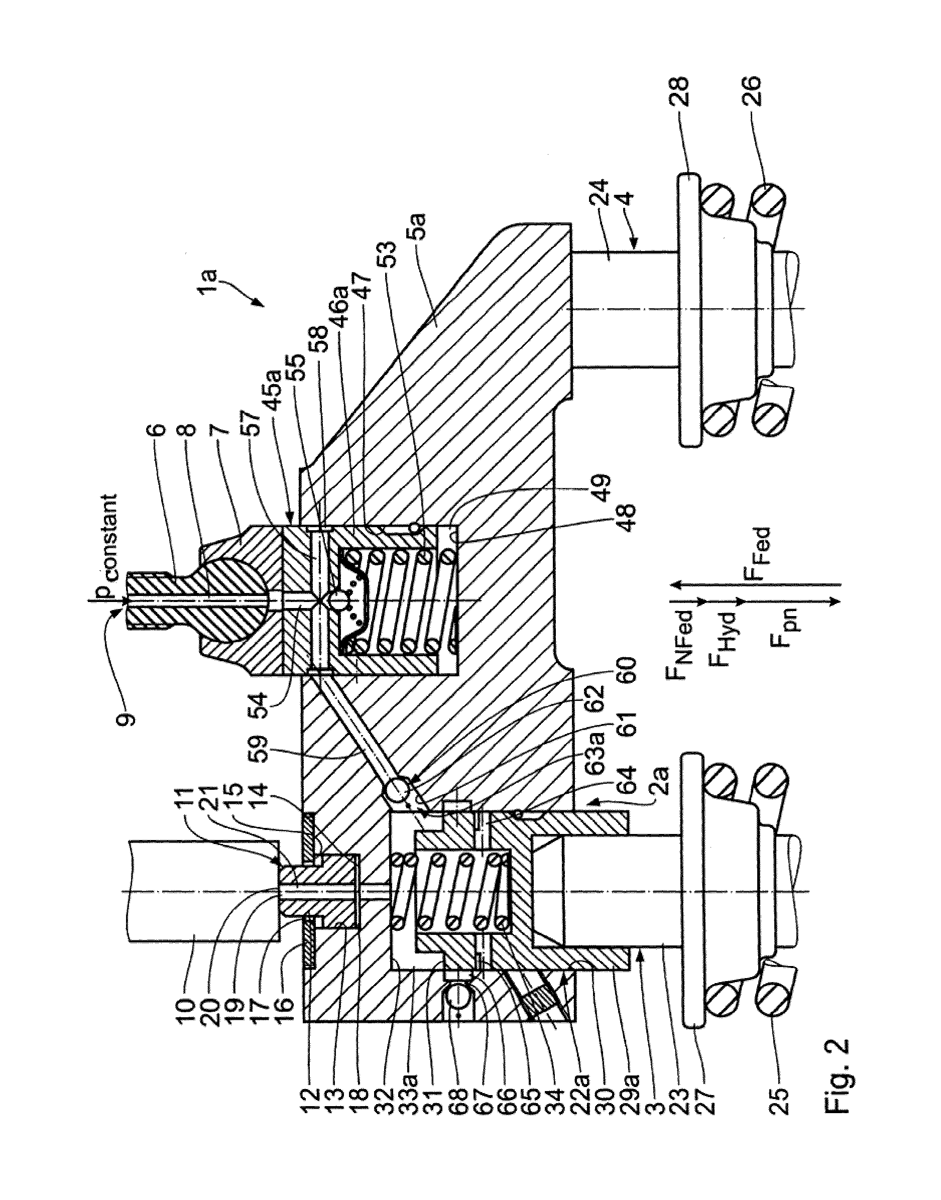
[0056]During the return stroke of the rocker arm, and after the renewed contact closure between the counter support 10 and the first piston 12, the gradual shutoff opening 20 is closed off, and the first piston 12 is displaced back in the direction of its upper dead center position until the valve bridge 5b is in its upper dead center position. The oil displaced out of the oil pressure chamber 18 is gradually shutoff via the first oil channel 21, the control pressure chamber 33b, the through-bore 64, and the shutoff opening 67, in conformity with the At the end of the fourth stroke, the counter support 10 again rests against the first piston 12, and the rocker arm has again reached the cam base circle. The EVB-play is compensated for, and a new braking cycle can begin.

[0057]In the normally fired engine operation, the control piston 29b is in its upper dead center position, so that the control piston 29b acts as a closure element 63b for the fourth oil channel 59b. The oil pressure ...

fourth embodiment

[0058]the invention will be described subsequently with the aid of FIG. 4. Structurally identical components have the same reference numerals as with the preceding embodiments, to the description of which reference is hereby made. Structurally different, yet functionally identical components have the same reference numerals, followed by the letter c. The essential difference relative to the preceding embodiments is that the first piston / cylinder unit 11c is integrated with the second piston / cylinder unit (valve auxiliary control unit 22c). The first piston 12c is axially movably guided in the control piston 29c, which acts as a cylinder. The oil pressure chamber 18c is delimited by the first piston 12c and the control piston 29c. The first oil channel 21c has a stepped configuration in the first piston 12c, and connects the oil pressure chamber 18c with the gradual shutoff opening 20. The first oil channel 20c is connected with the control pressure chamber 33c by means of a through-...


PUM


Abstract

An internal combustion engine including at least one exhaust valve for withdrawal of exhaust gas from at least one combustion chamber, and an engine brake device having a hydraulic valve auxiliary control unit by means of which the exhaust valve can be held in a temporarily open position when the engine brake device is actuated. The engine also includes a hydraulic valve play compensation mechanism for the exhaust valve, and an oil channel that for supplying oil to the valve auxiliary control unit is formed between the latter and the valve play compensation mechanism. For compensation of valve play of the exhaust valve, the oil channel can be closed off via a closure unit.

Description

[0001]The instant application should be granted the priority date of Jul. 11, 2008 the filing date of the corresponding German patent application 10 2008 032 773.5 as well as the priority date of Dec. 10, 2008, the filing date of German patent application 10 2008 061 412.2.BACKGROUND OF THE INVENTION[0002]The present invention relates to an internal combustion engine having at least one exhaust valve for the withdrawal of exhaust gas from at least one combustion chamber. The internal combustion engine also includes an engine brake device that is provided with a hydraulic valve auxiliary control unit that is integrated into a connection mechanism for connection of the exhaust valve with a rocker arm. The internal combustion engine is connected to an oil circuit for the supply of oil. By means of the valve auxiliary control unit, when the engine brake device is actuated the exhaust valve is adapted to be held in a temporarily open position.[0003]Internal combustion engines of this gen...

Claims


Application Information

Patent Timeline
Patent Type & Authority Patents(United States)
IPC IPC(8): F02D13/04
CPCF01L1/26F01L13/06
Inventor DILLY, HANS-WERNER
Owner MAN TRUCK & BUS AG
Why Eureka
Try Eureka