Thermoelectric heat pump

a heat pump and thermoelectric technology, applied in the field of thermoelectric devices, can solve the problems of various drawbacks of existing te device enclosures and assemblies, and achieve the effect of reducing or minimizing the number of spatially separated devices

Inactive Publication Date: 2009-12-10
GENTHERM INC
View PDF101 Cites 27 Cited by
  • Summary
  • Abstract
  • Description
  • Claims
  • Application Information

AI Technical Summary

Benefits of technology

[0020]The first heat exchanger can include at least one overhanging portion that protrudes past the at least one high temperature junction and the second heat exchanger includes at least one overhanging portion that protrudes past the at least one low temperature junction. The channel enclosure can include projections configured to nestle between the overhanging portions of the first heat exchanger and the overhanging portions of the second heat exchanger, the projections configured to contact the heat transfer region at boundaries between high temperature portions of the heat transfer region and low temperature portions of the heat transfer region such that leakage between the waste fluid channel and the main fluid channel at the junction between the channel enclosure and the heat transfer region is substantially minimized.
[0023]The channel enclosure can include projections configured to contact the heat transfer region at boundaries between the high temperature portion of the heat transfer region and the low temperature portion of the heat transfer region such that leakage between the waste fluid channel and the main fluid channel at the junction between the channel enclosure and the heat transfer region is substantially minimized.
[0035]In some embodiments, a plurality of ports for moving fluid into or out from the waste channel and the main channel are stacked in a first direction. In at least some of said embodiments, alternating high and low temperature portions of the heat transfer region are arranged in a second direction, where the second direction is substantially perpendicular to the first direction. In some embodiments, the high temperature portion of the heat transfer region includes a plurality of spatially separated high temperature regions. In some embodiments, the low temperature portion of the heat transfer region includes a plurality of spatially separated low temperature regions. In certain embodiments, thermoelectric modules are positioned and / or oriented to decrease or minimize the number of spatially separated high temperature regions and low temperature regions.

Problems solved by technology

Existing TE device enclosures and assemblies suffer from various drawbacks.

Method used


Image

  • Thermoelectric heat pump
  • Thermoelectric heat pump
  • Thermoelectric heat pump

Examples


Embodiment Construction

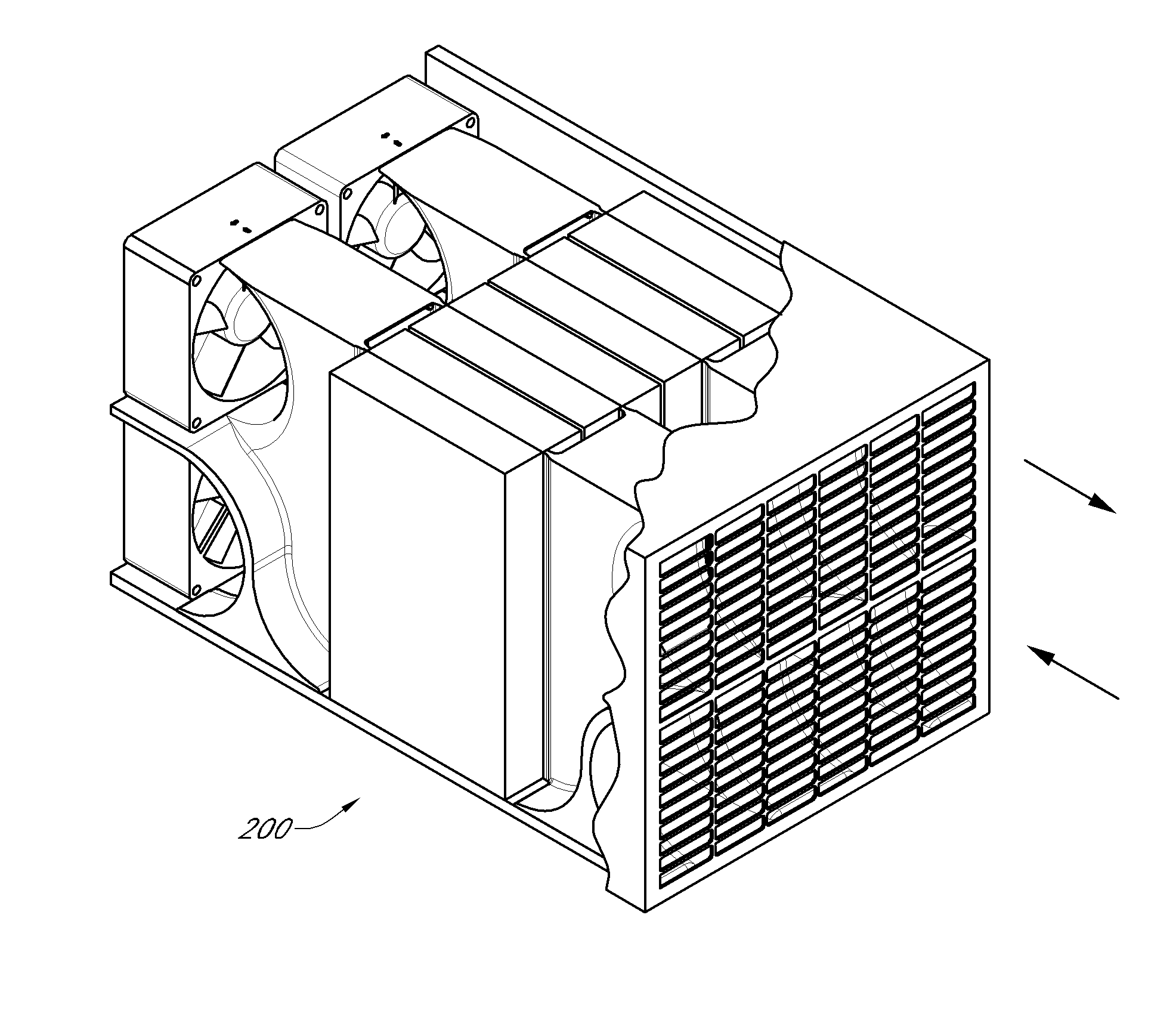
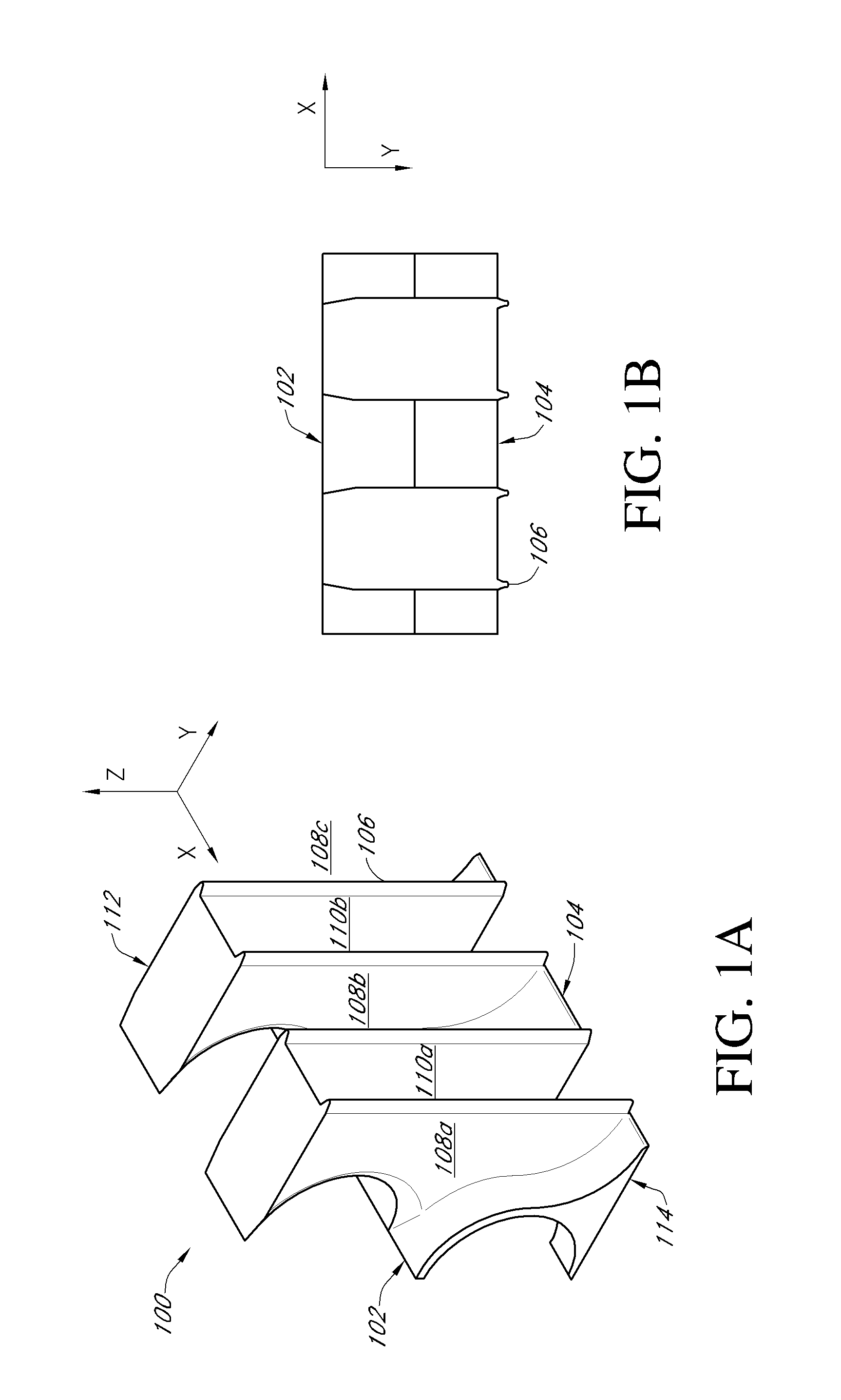
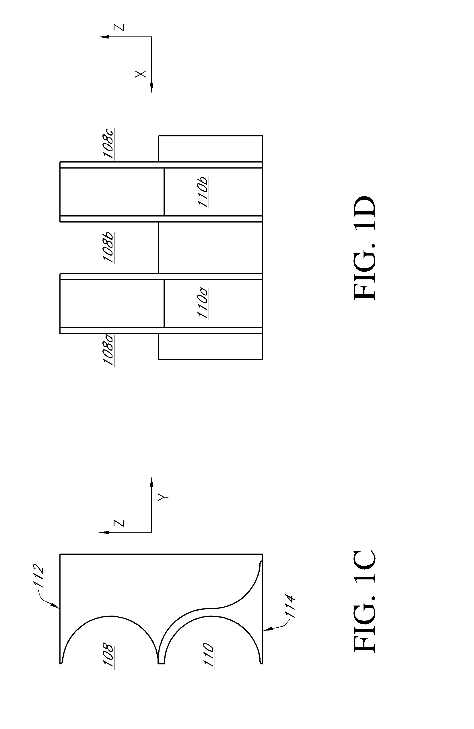
[0073]A TE heat pump includes one or more TE modules that transfer heat against the thermal gradient from one junction (e.g., a low-temperature junction or main junction) to another (e.g., a high-temperature junction or waste junction). One or more suitable TE materials can be used for this purpose. A first defined channel provides a passageway for waste fluid flow, where the fluid is placed in substantial thermal communication with the high-temperature junction. Fluid flowing in the first defined channel can remove heat from the high-temperature junction. In some embodiments, the waste channel is in communication with a fluid reservoir (e.g., a reservoir in the external environment, such as the atmosphere) or other heat sink. Using a fluid to assist in removal of thermal energy from the high-temperature junction can improve the efficiency of a TE heat pump. The waste channel can be enclosed by any suitable structure, such as, for example, a material that has a low coefficient of th...


PUM

PropertyMeasurementUnit
widthaaaaaaaaaa
widthaaaaaaaaaa
widthaaaaaaaaaa

Abstract

In certain embodiments, a thermoelectric heat pump includes a heat transfer region having an array of thermoelectric modules, a waste channel in substantial thermal communication with a high temperature portion of the heat transfer region, and a main channel in substantial thermal communication with a low temperature portion of the heat transfer region. An enclosure wall provides a barrier between fluid in the waste channel and fluid in the main channel throughout the interior of the thermoelectric heat pump. In some embodiments, the waste fluid channel and the main fluid channel are positioned and shaped such that differences in temperature between fluids disposed near opposite sides of the enclosure wall are substantially decreased or minimized at corresponding positions along the channels.

Description

RELATED APPLICATIONS[0001]This application claims the benefit under 35 U.S.C. § 119(e) of U.S. Provisional Patent Application No. 61 / 058,482, titled “Thermoelectric Device Enclosures with Improved Fluid Channeling,” filed Jun. 3, 2008, and U.S. Provisional Patent Application No. 61 / 087,611, titled “Improved Thermoelectric Device Enclosures,” filed Aug. 8, 2008. This application is related to U.S. Application Ser. No. (Atty Docket: BSST.036A1), concurrently filed with this application. The entire contents of each of the above-identified applications are incorporated by reference herein and made a part of this specification.BACKGROUND[0002]1. Field[0003]This disclosure relates to the field of thermoelectric devices and, in particular, to improved thermoelectric device enclosures and assemblies.[0004]2. Description of Related Art[0005]Certain thermoelectric (TE) devices, sometimes called Seebeck-Peltier devices, Peltier devices, thermoelectric engines, thermoelectric heat exchangers or...

Claims


Application Information

Patent Timeline
Patent Type & Authority Applications(United States)
IPC IPC(8): F25B21/02
CPCF25B21/02Y10T29/4935F25B2321/0251
Inventor BELL, LON E.DILLER, ROBERT W.
Owner GENTHERM INC
Why Eureka
Try Eureka