Reactor multi-pass grids for improved catalyst hydrodynamics

Active Publication Date: 2014-10-02
UOP LLC
View PDF4 Cites 13 Cited by
  • Summary
  • Abstract
  • Description
  • Claims
  • Application Information

AI Technical Summary

Benefits of technology

[0009]The present invention is a process and device for improving the contact and yields of light olefins generated in an oxygenate conversion process. The apparatus comprises a plurality of grids disposed within the reactor, where the grids are compr

Problems solved by technology

The increasing demand for light olefins has led to the sear

Method used


Image

  • Reactor multi-pass grids for improved catalyst hydrodynamics
  • Reactor multi-pass grids for improved catalyst hydrodynamics

Examples


Embodiment Construction

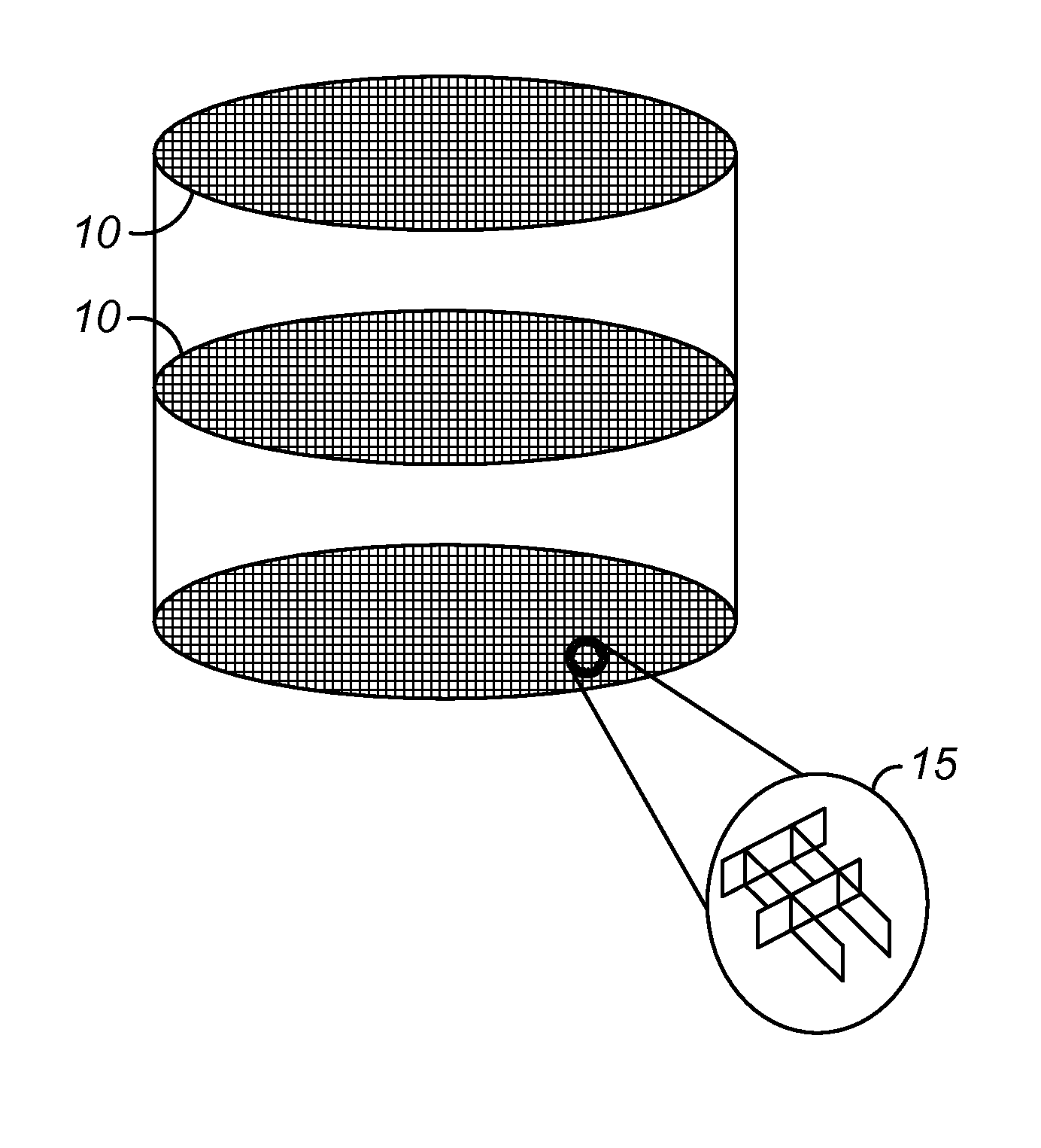
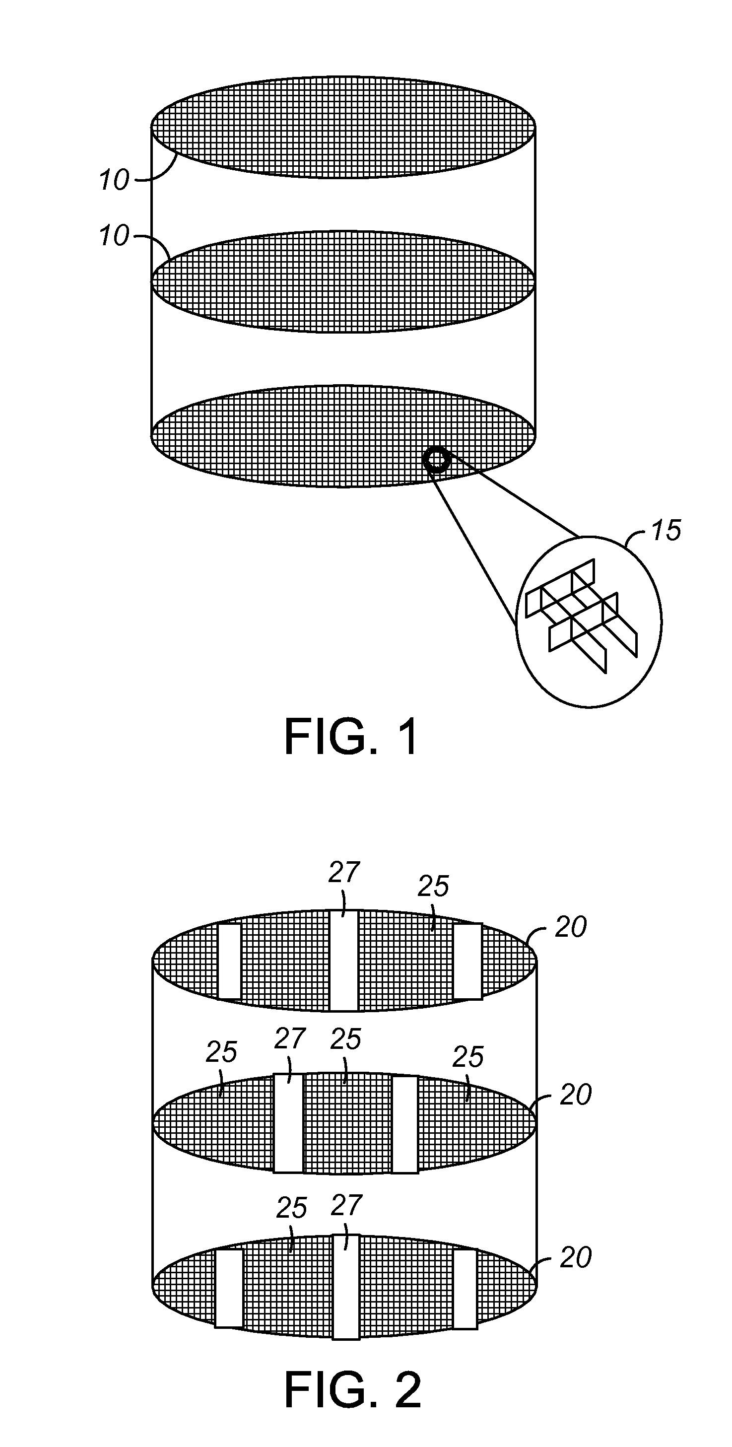
[0014]There are many reactor processes that utilize fluidized catalyst beds. The catalyst beds are fluidized for providing good contact between the catalyst and reactants. A methanol to olefins (MTO) reactor utilizes a deep catalyst bed. Along with improving the catalyst, improving the conditions within the reactor are also important. The catalyst bed in the MTO is a deep fluidized catalyst bed and flows downward through the reactor. Deep catalyst bed can develop regions where the catalyst does not flow well, and where gas can be maldistributed within the reactor. To improve the movement of catalyst within the reactor and the flow and contact with the gas reactants, vertical plates, or grids, were placed within the reactors. The grids contributed to improving the uniformity of catalyst within the reactor bed. This leads to improve product yields. The grids extend horizontally across the reactor bed and are positioned at multiple elevations within the catalyst bed.

[0015]The grids are...


PUM


Abstract

A process and device for the flow of catalyst in a reactor is presented. The device includes a series of grids within a reactor vessel, where each grid includes small openings for the passage of gas and some catalyst particles, and larger openings for the more continuous passage of catalyst. The grids span horizontally across the vessel, and are spaced vertically apart to provide for the flow of catalyst down through the reactor

Description

CROSS REFERENCE TO RELATED APPLICATION[0001]This application claims the benefit of U.S. Provisional Application No. 61 / 806,486 filed on Mar. 29, 2013.FIELD OF THE INVENTION[0002]The present invention relates to processes and apparatuses utilizing reactor internals for the distribution of catalysts in a reactor. Specifically, this invention relates to designs for the internals of an MTO reactor to provide for a better distribution of catalyst and contacting of the catalyst with the reactants.BACKGROUND OF THE INVENTION[0003]Ethylene and propylene, or light olefins, are important for the production of commercially important plastics, namely polyethylene and polypropylene. Other important polymer precursors include vinyl chloride, ethylbenzene, ethylene oxide and other compounds, which are derived from the light olefins. The production of light olefins is primarily produced through the cracking of heavier hydrocarbons from hydrocarbon feedstocks derived from petroleum.[0004]A light ole...

Claims


Application Information

Patent Timeline
IPC IPC(8): B01J8/18
CPCB01J8/1881B01J8/082B01J8/12B01J2208/00663B01J2208/00681B01J2208/0084B01J2208/00884B01J2208/00938
Inventor JOHNSON, II, RICHARD A.PALMAS, PAOLOSENETAR, JOHN J.KAUFF, DANIEL A.STINE, MICHAEL
Owner UOP LLC
Why Eureka
Try Eureka