Methods and devices for applying energy to bodily tissues

a technology of bodily tissues and energy, applied in the field of medical elements, can solve the problems of unmet needs for improved devices and methods, non-uniform lesion profiles along the length of the antenna, and heating of the device shaft, and achieve the effect of improving the cosmetic appearance of skin

Active Publication Date: 2010-06-03
MICROCUBE
View PDF34 Cites 172 Cited by
  • Summary
  • Abstract
  • Description
  • Claims
  • Application Information

AI Technical Summary

Benefits of technology

[0015]The one or more additional shaping elements in the antenna may be used to create a more uniform microwave field distributed over a larger region. The one or more shaping elements in the antenna may also be used to improve the power deposition by the antenna. One or both of radiating element and shaping element may be enclosed in an antenna dielectric material In several of the embodiments disclosed herein, a conductive element (e.g. a length of metallic wire) electrically connected to the outer conductor of a coaxial cable is used to shape the microwave field.
[0019]The antennas disclosed herein may be deployed from an insertion configuration to a working configuration before being placed in the vicinity or inside of the target tissue. Alternately, the antennas may be deployed from an insertion configuration to a working configuration after being placed in the vicinity or inside of the target tissue. The deployment of the antennas disclosed herein may be done by one of several methods. The antennas herein may be navigated to the target tissue in a fully deployed configuration. In one embodiment, an antenna is navigated to the surface of an abdominal organ e.g. the liver in a fully deployed configuration through a laparotomy. In another embodiment, an antenna disclosed herein is deployed through an introducer in which the antenna is in a collapsed, low-profile configuration when inside the introducer and is deployed to a working configuration after the antenna exits the introducer. The antenna may be deployed after the antenna exits the introducer by one or more of: the elastic property of the antenna or its components, the super-elastic property of the antenna or its components, the shape memory property of the antenna or its components, use of a mechanical deployment mechanism for the antenna or its components, use of one or more anatomical regions to change the shape of one or more antenna portions, etc. One or more portions of the antennas herein may be malleable or plastically deformable. This allows the user to shape an antenna to ensure better contact with target tissue or better navigation through the anatomy.

Problems solved by technology

Even though devices and methods exist to treat these conditions by ablating tissue, there is still an unmet need for improved devices and methods.
Many of the existing antennas have common disadvantages such as device shaft heating and non-uniform lesion profile along the length of the antenna.
It is characterized by excessive menstrual blood loss.
The condition severely affects the quality of life of the affected women since it may interfere with physical activity, work and sexual activity.
Every current endometrial ablation technique has some fundamental limitations.
For example, the Hydrothermablator™ device by Boston Scientific needs a hysteroscope which adds to the procedure cost and complexity.
Further the device is thick and rigid.
Thus a significant amount of cervical dilation is needed to introduce the device into the uterine cavity.
Since cervical dilation is very painful, the procedure requires significant anesthesia, usually in the form of conscious sedation or general anesthesia.
Also, the device is expensive (˜$900).
It is difficult to use a single monopole antenna to ablate tumors that have a thickness or diameter of a few centimeters in a sufficiently short time.
For many cancer-related applications, the targeted tumors have an excessive size (e.g. diameter of several centimeters) and a single monopole antenna is of limited use.
This increases the complexity of the ablation system.
The overall size and cost of the ablation device will also be increased due to more number of elements employed in the system.
Also, this increases the invasiveness and complexity of the procedure.
This in turn carries a risk of damaging healthy tissue by the microwave energy.
The creation of such multiple, connecting point lesions is very time consuming and technically challenging.
There are other limitations to point ablation systems.
For example, during the translation of the ablation tip to a new location, the distal ablation tip may slip, or otherwise move across the target tissue in an undesired manner.
The steps of translation of the ablation tip to a new location are further complicated by the motion of the left atrium because of the natural beating of the heart.
Further, users of point ablation systems typically use costly support equipment to provide historic and current position information of the ablating portion with respect to anatomical cardiac structures and previously created lesions.
The support equipment is extremely costly and requires additional personnel to operate, ultimately increasing procedure costs.
Still another problem with point ablation devices having ablating tip portions is the risk of perforation.
This in turn may result in perforation of the atrial wall which in turn may lead to formation of a potentially fatal atrio-esophageal fistula.
This is difficult to achieve using the prior art delivery systems leading to inconsistent contact between the RF electrode(s) and the target tissue.
Such inconsistent electrode contact causes variability in the transmission of energy throughout the target length of ablated coagulated tissue.
This inconsistency also produces undesirable gaps of viable tissue that promote propagation of wavelets that sustain atrial fibrillation, or produce atrial flutter, atrial tachycardia, or other arrhythmia substrate.
Thus, even though several methods and devices exist that treat clinical conditions by energy delivery, there are still unmet needs for improved methods and devices.

Method used


Image

  • Methods and devices for applying energy to bodily tissues
  • Methods and devices for applying energy to bodily tissues
  • Methods and devices for applying energy to bodily tissues

Examples


Embodiment Construction

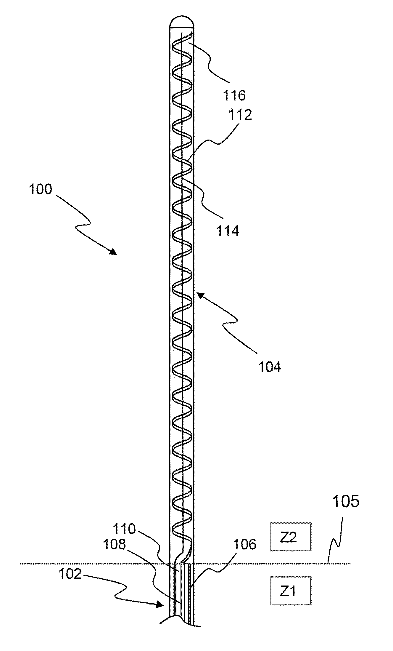
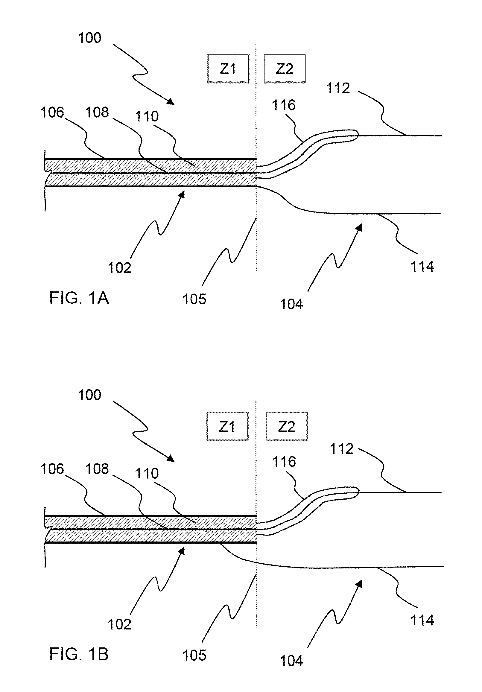
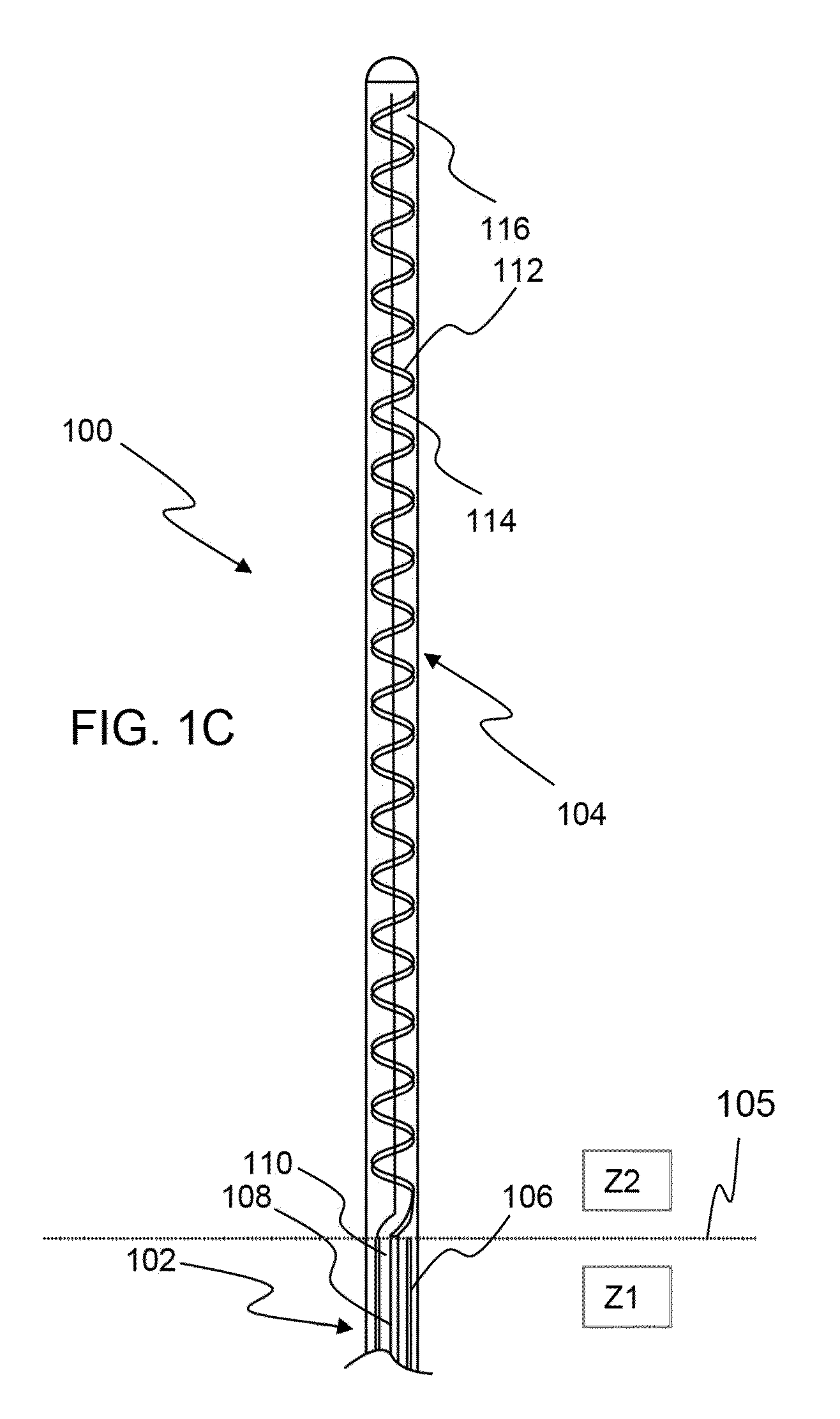
[0097]This specification discloses multiple antenna designs, systems, structures and devices, and associated methods, which illustrate various aspects of the invention. The various microwave antennas and the microwave engineering principles disclosed herein may be used in a variety of non-medical and medical applications. The near field of the microwave antennas disclosed herein may be used on target materials such as food, industrial products, semiconductors, etc. The near field of the microwave antennas disclosed herein may be used for cooking or heating foods, in industrial processes for drying and curing products, in semiconductor processing techniques to generate plasma for processes such as reactive ion etching and plasma-enhanced chemical vapor deposition (PECVD). While these systems, structures and devices, and associated methods, are discussed primarily in terms of some particular clinical applications (e.g. ablating cardiac tissue to treat arrhythmias, endometrial ablation...


PUM


Abstract

Devices and methods for treating tissue with microwave energy used in applications such as destroying a soft tissue by microwave ablation and / or creating point, line, area or volumetric lesions. Various embodiments of flexible, low-profile devices are also disclosed where such device can be inserted non-invasively or minimally invasively near or into the target tissue such as cardiac tissue. The devices disclosed herein comprise antennas wherein the field profile generated by an antenna is tailored and optimized for a particular clinical application. The antennas use unique properties of microwaves such as interaction of a microwave field with one or more conductive or non-conductive shaping elements to shape or redistribute the microwave field.

Description

CROSS-REFERENCE TO RELATED APPLICATIONS[0001]This application is a nonprovisional of U.S. Patent Provisional Nos. 61 / 107,252 filed on Oct. 21, 2008, 61 / 162,241 filed on Mar. 20, 2009, 61 / 180,133 filed on May 21, 2009, and 61 / 222,409 filed on Jul. 1, 2009 the content of each of which are incorporated herein by reference in their entirety.FIELD OF THE INVENTION[0002]This invention relates to medical elements (e.g. microwave ablation antennas), usable for performing diagnostic and / or therapeutic procedures on or within a patient's body.BACKGROUND OF THE INVENTION[0003]There is a need for improved devices and methods to treat several medical conditions. Several conditions including atrial fibrillation, cancer, Menorrhagia, wrinkles, etc. may be treated by ablating tissue by applying an ablating energy. Even though devices and methods exist to treat these conditions by ablating tissue, there is still an unmet need for improved devices and methods.[0004]For example, microwave antennas (e....

Claims


Application Information

Patent Timeline
Patent Type & Authority Applications(United States)
IPC IPC(8): A61B18/18
CPCA61B18/18A61B2018/00761A61B2018/1861A61B2018/00351A61B2018/00422A61B2018/00452A61B2018/00488A61B2018/00511A61B2018/00517A61B2018/00523A61B2018/00529A61B2018/00547A61B2018/00559A61B2018/00577A61B2018/00702A61B2018/00726A61B2018/00791A61B2018/00839A61B2018/00875A61B2018/00982A61B2018/00994A61B2018/1846A61B2018/1853A61B2018/1869A61B18/1815
Inventor SHROFF, KETANCHU, CHUN YIUMODY, DINESH I.EMMONS, CLARENCEWALKE, AMRISH JAYPRAKASH
Owner MICROCUBE
Why Eureka
Try Eureka