[0008] A method in accordance with the present invention allows uniform coating of internal surfaces of a
pipe, tube or other workpiece by using the workpiece itself as a
deposition chamber and using flow reversal of coating material within the workpiece. The method includes
coupling at least a first opening of the
pipe to a
gas supply subsystem to function as an entrance and
coupling at least a second opening of the
pipe to a pumping subsystem to function as the exit. In a first coating cycle, gas is flowed through the pipe from the first opening (entrance) to the second opening (exit). Then, with the pipe remaining in place, the flow of gas through the workpiece is reversed to accomplish a second coating cycle. In some embodiments, the method and the
system for implementing the method are used to provide reverse-cycle coating for a workpiece with more than two openings. On the other hand, the reverse-cycle coating method may be applied to workpieces with a single opening, if the
cycling is via a device that is inserted into the workpiece.
[0012] For the reverse-cycle coating process, the gas flow and the pumping speed preferably are adjusted such that the pressure provides a hollow
cathode environment in the workpiece upon application of a
voltage bias. This pressure is such that the
electron mean free path is slightly less than the
diameter of the tube, causing electrons to oscillate across the tube and resulting in multiple ionizing collisions and a more intense
plasma. This provides an improvement relative to prior art PECVD approaches in which
plasma is generated externally from a workpiece, resulting in a loss of
ionization as gas flows through the tube, so that less film deposition occurs toward the exit from the workpiece. The hollow
cathode effect, being dependent on pressure, the
plasma density and consequently the film thickness and quality will vary along the length of the tube if the pressure drop across the tube becomes too large. In comparison, as a consequence of the flow reversal, the invention achieves a more uniformly ionized plasma along the length of the workpiece, thereby providing a more uniform deposition. Improvement in deposition uniformity is accomplished by controlling the pressure drop across the workpiece and implementing the reverse-cycle coating process to provide a uniform plasma.
[0013] The method allows coating of interior surfaces of pipes, tubes, valves, pumps or other workpieces with more complex geometries. While the openings may be referred to as “entrances” and “exits,” these roles are reversed when the direction of flow is reversed. The flow
cycling significantly reduces the possibility of an end-to-end decline in coating thickness as a consequence of a gradual reduction of the density of coating material in the plasma as the coating material is drawn from the plasma to the internal surface or surfaces of the workpiece. The improvement of end-to-end coating thickness is also due to the gas reservoirs providing fresh reactant gas at each workpiece opening, that can flow or diffuse into the pipe as the gas is consumed or depleted within the pipe during the coating process.
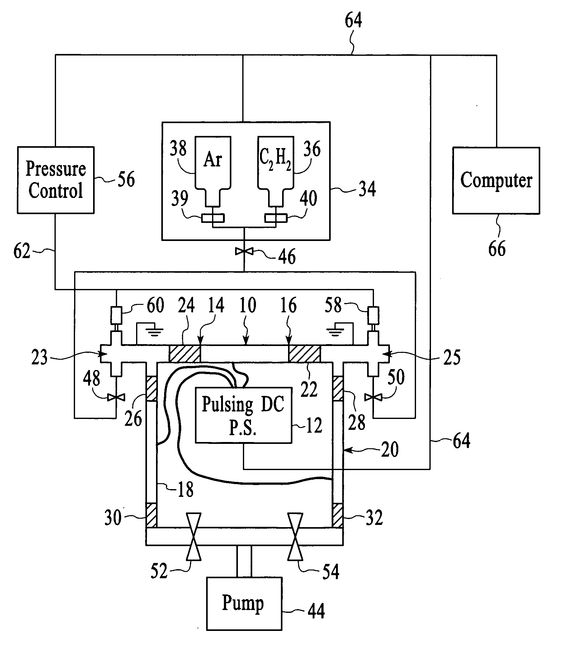
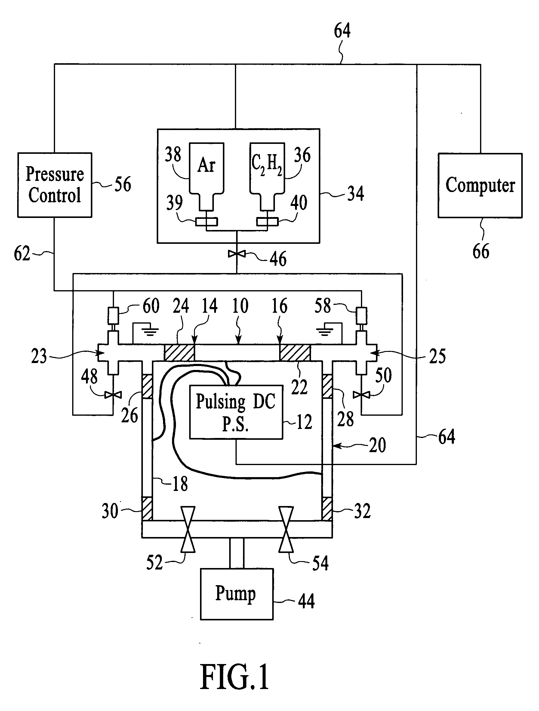
[0015] In some embodiments, the biasing system is also cycled. A negative
pulsed DC voltage is applied so as to have a
duty cycle that is selected such that (1) when the voltage is “on,” a
negative voltage is applied to the workpiece such that positive source gas ions are attracted to the internal surfaces and react chemically to coat the internal surfaces of the workpiece, and (2) when the voltage is “off,” the positive source gas ions are sufficiently replenished within the interior of the workpiece to provide uniformity in coating the internal surfaces. If the coating material is an insulator, the “off” condition of the
duty cycle may include a reverse voltage that is sufficient to deplete
surface charges resulting from the coating of the internal surfaces of the workpiece.
[0016] Where the workpiece includes at least two openings, anodes may be coupled to each opening, with the anodes being physically and electrically isolated from the workpiece by retractable seals. Also, a gas reservoir is coupled to each opening, such that the
gas pressure at each opening can be controlled by means of the flow into the reservoir from the gas source and the flow out of the gas reservoir either into the pipe or to the pump. Thus, the pressure gradient across the pipe can be precisely controlled.
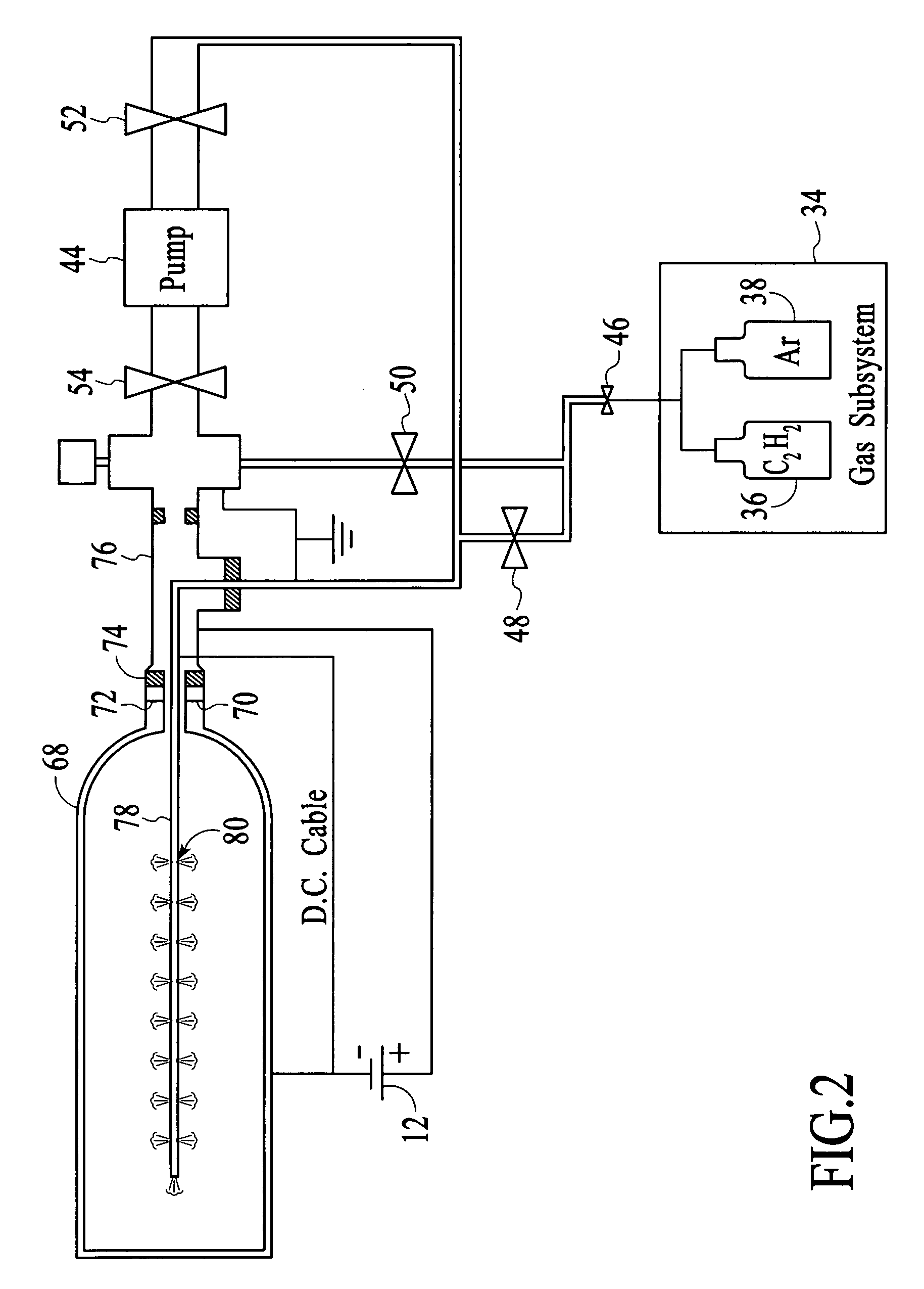
[0017] In another embodiment of the invention, a device is inserted into the workpiece and is used to implement the reverse-cycle coating method. The device includes at least one hole to enable gas flow to and from the device. In one cycle, the gas is flowed from the inserted device, through the conductive workpiece, and out an opening of the workpiece. This embodiment is particularly well suited for coating internal surfaces of a workpiece having a single opening. The flow of gas may be reversed, so that the flow is through the workpiece to the device. The device may include a tube that is adjustable in length and that includes a number of holes, with the number varying as the length is adjusted. This adjustability enables the device to be used to efficiently coat workpieces of various sizes.

