Conforming-electrode catheter and method for ablation

a technology of electrode electrodes and catheters, applied in the field of conforming electrode electrode catheters, can solve the problems of large temperature gradients and hot spots, undesirable coagulation and charring of surface tissue, and may encounter several difficulties, so as to reduce the amount of conductive fluid, reduce the formation of undesirable coagulation and charring of surface tissue, and mitigate the effect of electrode-tissue contact problems

Inactive Publication Date: 2008-02-05
ST JUDE MEDICAL ATRIAL FIBRILLATION DIV
View PDF9 Cites 173 Cited by
  • Summary
  • Abstract
  • Description
  • Claims
  • Application Information

AI Technical Summary

Benefits of technology

[0011]It is desirable to be able to form adequately-deep spot or continuous linear lesions in tissue while reducing the formation of undesirable coagulum and charring of the surface tissue, while applying a reasonable amount of RF energy, while mitigating electrode-tissue contact problems, and / or while reducing the amount of conductive fluid (e.g., isotonic saline) possibly entering a patient's bloodstream during the procedure. The present invention is an improved ablation electrode catheter.
[0012]In one form, the present invention comprises a wet-brush electrode that facilitates electrode-tissue contact in target tissue having contoured surfaces. The wet-brush electrode comprises a plurality of flexible filaments adapted to transfer ablative energy to target tissue, the flexible filaments having longitudinal axes and defining interstitial spaces among the plurality of filaments, wherein the interstitial spaces are adapted to direct conductive fluid predominantly parallel to the filament longitudinal axes. This wet-brush electrode also comprises a primary conductor operatively connected to, and adapted to transfer ablative energy to, the plurality of flexible filaments; and a fluid-delivery means adapted to deliver conductive fluid to the interstitial spaces.

Problems solved by technology

Several difficulties may be encountered, however, when attempting to form adequately-deep lesions at specific locations using some existing ablation electrodes.
At the edges of some existing electrodes are regions of very high current density, leading to large temperature gradients and hot spots.
These “edge effects” may result in the formation of undesirable coagulum and charring of the surface tissue.
For example, undesirable coagulum may begin to form when blood reaches around 80° C. for an appreciable length of time, and undesirable tissue charring and desiccation may be seen when tissue reaches around 100° C. for an appreciable length of time.
There two types of undesirable coagulum: coagulum that adheres to and damages the medical device; and coagulum blood clots or curds that may enter a patient's bloodstream, possibly resulting in other health problems for the patient.
Charring of the surface tissue may also have deleterious effects on a patient.
As the temperature of the electrode is increased, the contact time required to form an adequately-deep lesion decreases, but the likelihood of charring surface tissue and forming undesirable coagulum increases.
As the temperature of the electrode is decreased, the contact time required to form an adequately-deep lesion increases, but the likelihood of charring surface tissue and forming undesirable coagulum decreases.
Active temperature control may help, but the placement of thermocouples, for example, is tricky and setting the RF generator for a certain temperature becomes an empirical exercise as actual tissue temperatures are generally different from those recorded next to the electrode due to factors such as convection and catheter design.
Another difficulty encountered with existing ablation electrodes is how to ensure adequate tissue contact.
All of these devices comprise rigid electrodes that do not always conform to the tissue surface, especially when sharp gradients and undulations are present, such as at the ostium of the pulmonary vein in the left atrium and the isthmus of the right atrium.
Consequently, continuous linear lesions are difficult to achieve.
When forming lesions in a heart, the beating of the heart further complicates matters, making it difficult to keep adequate contact between the electrode and the tissue for a sufficient length of time to form a desired lesion.
With a rigid electrode, it can be quite difficult to maintain sufficient contact pressure until an adequate lesion has been formed.
This problem is exacerbated on contoured or trabeculated surfaces.
If the contact between the electrode and the tissue cannot be properly maintained, a quality lesion is unlikely to be formed.
Catheters based upon a virtual electrode may address some of the difficulties, but these catheters often require high flow rates of conductive fluid (e.g., typically around 70 milliliters per minute) to maintain effective cooling for high-power RF applications.
The introduction of a large amount of conductive fluid into a patient's bloodstream may have detrimental effects on the patient.

Method used


Image

  • Conforming-electrode catheter and method for ablation
  • Conforming-electrode catheter and method for ablation
  • Conforming-electrode catheter and method for ablation

Examples


first embodiment

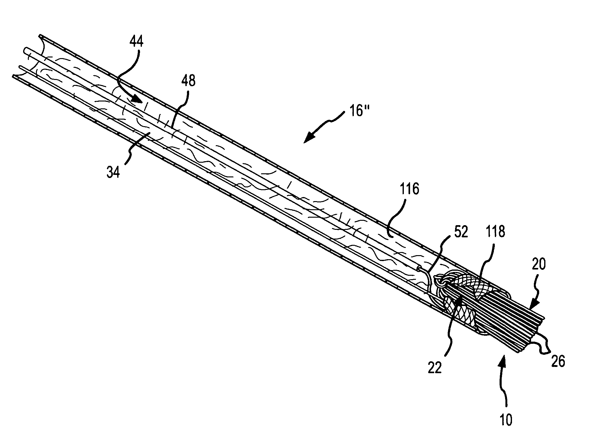
[0082]FIG. 26 is a cross-sectional view of a shielded-tip brush electrode 120. In this embodiment, the uninsulated portion 52 of the primary conductor 48 is looped around the outer surface of the brush electrode after passing through a mechanical interface 122 supporting the filaments 26 of the brush electrode adjacent to the distal end 124 of an inner sheath 126. Since fluid may or may not travel through the lumen 128 of the inner sheath 126, the mechanical interface 122 may or may not be porous. In the embodiment depicted in FIG. 26, there is an outer sheath 130 surrounding the inner sheath 126. The inner sheath houses the primary conductor 48 and supports the mechanical interface 122 for the filaments 26 of the brush electrode 120. The primary conductor again includes an uninsulated portion 52 that transfers ablative energy 150 (e.g., RF energy) to the conductive filaments in the brush electrode 120. As mentioned, in this embodiment the uninsulated portion 52 of the primary condu...

second embodiment

[0084]FIG. 27 is similar to FIG. 26, but depicts a shielded tip brush electrode 120′. The only differences between the embodiment depicted in FIG. 26 and the embodiment depicted in FIG. 27 are the size of the fluid jacket 138′ and the configuration of the flexible polymer nipple or boot 142′ that supports the brush filaments. In the embodiment depicted in FIG. 27, an alternative flexible polymer nipple or boot 142′ defines a smaller fluid jacket 138′ and supports the filaments in a band of direct contact extending around the perimeter of the filament bundle. The band of direct contact 152 supports the filaments over a larger section of the outer surface of the brush electrode than does the ring of direct contact 144 depicted in FIG. 26. By adjusting the configuration of the flexible polymer nipple or boot in this manner, the amount of conductive fluid flowing into the brush electrode and the overall flexibility of the brush electrode can be manipulated.

[0085]It should be noted that,...


PUM


Abstract

A brush electrode catheter and a method for using the brush electrode catheter for tissue ablation are disclosed. The brush electrode catheter comprises a plurality of flexible filaments or bristles for applying ablative energy (e.g., RF energy) to target tissue during the formation of spot or continuous linear lesions. Interstitial spaces are defined among the filaments of the brush electrode, and the interstitial spaces are adapted to direct conductive or nonconductive fluid, when present, toward the distal ends of the brush filaments. The brush electrode facilitates electrode-tissue contact in target tissue having flat or contoured surfaces. The flexible filaments may be selectively trimmed to give a desired tip configuration or a desired standoff distance between the tissue and the conductive filaments in the brush electrode. Also, the filaments may be grouped into clusters. A shielded-tip brush electrode, including a flexible boot, is also disclosed.

Description

CROSS-REFERENCE TO RELATED APPLICATIONS[0001]This application is a continuation-in-part of U.S. application Ser. No. 10 / 808,919, filed 24 Mar. 2004 (the '919 application), now pending, which claims the benefit of U.S. provisional application No. 60 / 537,092, filed 16 Jan. 2004, (the '092 application). The '919 and '092 applications are hereby incorporated by reference as though fully set forth herein. U.S. application Ser. No. 10 / 856,925 (the '925 application), filed May 27, 2004 is also a continuation-in-part of the '919 application and also claims priority pursuant to 35 U.S.C. §119(e) to the '092 application. U.S. application Ser. No. 11 / 190,724 (the '724 application), filed Jul. 27, 2005, is a continuation-in-part of each of the '919, '925, and the present application and also claims the benefit of priority to the '092 application.BACKGROUND OF THE INVENTION[0002]a. Field of the Invention[0003]The instant invention is directed toward a conforming-electrode catheter and a method f...

Claims


Application Information

Patent Timeline
Patent Type & Authority Patents(United States)
IPC IPC(8): A61B18/18A61B18/14
CPCA61B18/1402A61B2018/143A61B2018/1472
Inventor PAUL, SAURAVBELHE, KEDAR RAVINDRACAO, HONGTHAO, CHOU
Owner ST JUDE MEDICAL ATRIAL FIBRILLATION DIV
Why Eureka
Try Eureka