Spinal fusion implant and related methods

a technology of spinal fusion and implant, applied in the field of spinal fusion implants, can solve the problems of increasing the risk of infection and blood loss, reducing structural integrity at the donor site, and affecting the effect of cortical ring contact and avoiding dural impingemen

Active Publication Date: 2011-01-11
NUVASIVE
View PDF20 Cites 169 Cited by
  • Summary
  • Abstract
  • Description
  • Claims
  • Application Information

AI Technical Summary

Benefits of technology

[0012]The present invention overcomes the drawbacks of the prior art by providing a spinal fusion implant of non-bone construction. The non-bone construction of the spinal fusion implant provides an advantage in that it is not supply limited and does not require harvesting bone from the patient (as with allograft). The present invention better facilitates cortical ring contact and fit between anterior ring portions of vertebral endplates, provides-self distraction during insertion and rotation, and avoids dural impingement.
[0017]According to a further aspect of the present invention, the spinal fusion implant may be provided with one or more radiographic markers at the proximal and / or distal ends. These markers allow for a more detailed visualization of the implant after insertion (through radiography) and allow for a more accurate and effective placement of the implant.
[0018]According to a still further aspect of the present invention, the proximal end of the spinal fusion implant has a surface that is tapered (angled) to avoid dural impingement after implantation. Additionally, the tapered nature of the proximal surface can aid in overall fit of the spinal fusion implant within the intervertebral disc space. Significantly, the tapered proximal surface on the proximal end enables the spinal fusion implant 10 to maximize contact with the posterior portion of the cortical ring of each adjacent vertebral body.
[0019]According to a still further aspect of the present invention, the distal end of the spinal fusion implant has a conical (bullet-shaped) shape including a pair of first tapered (angled) surfaces and a pair of second tapered (angled) surfaces. The first tapered surfaces extend between the lateral surfaces and the distal end of the implant, and function to distract the vertebrae adjacent to the target intervertebral space during insertion of the spinal fusion implant. The second tapered surfaces extend between the top and bottom surfaces and the distal end of the spinal fusion implant, and function to maximize contact with the anterior portion of the cortical ring of each adjacent vertebral body. Furthermore, the second tapered surfaces provide for a better fit with the contour of the vertebral body endplates, allowing for a more anterior positioning of the spinal fusion implant and thus advantageous utilization of the cortical rings of the vertebral bodies.

Problems solved by technology

This method can be detrimental because it may not yield a sufficient quantity of graft material, requires additional surgery, and increases the risk of infection and blood loss.
Moreover, the structural integrity at the donor site can be reduced and significant morbidity associated with harvesting the autologous bone graft may occur.
Production of allograft bone implants may be difficult because of the inherent challenges in forecasting the receipt of cadavers.
Furthermore, allograft may only provide temporary support as it is difficult to manufacture the allograft with consistent shape and strength given the differing characteristics of cadavers.
Graft material usually has a smooth surface which does not provide good friction between the adjacent vertebrae and slippage of the graft may occur which can cause neural and vascular injury as well as collapse of the disc space.

Method used


Image

  • Spinal fusion implant and related methods
  • Spinal fusion implant and related methods
  • Spinal fusion implant and related methods

Examples


Embodiment Construction

[0037]Illustrative embodiments of the invention are described below. In the interest of clarity, not all features of an actual implementation are described in this specification. It will of course be appreciated that in the development of any such actual embodiment, numerous implementation-specific decisions must be made to achieve the developers' specific goals, such as compliance with system-related and business-related constraints, which will vary from one implementation to another. Moreover, it will be appreciated that such a development effort might be complex and time-consuming, but would nevertheless be a routine undertaking for those of ordinary skill in the art having the benefit of this disclosure. The spinal fusion implant disclosed herein boasts a variety of inventive features and components that warrant patent protection, both individually and in combination.

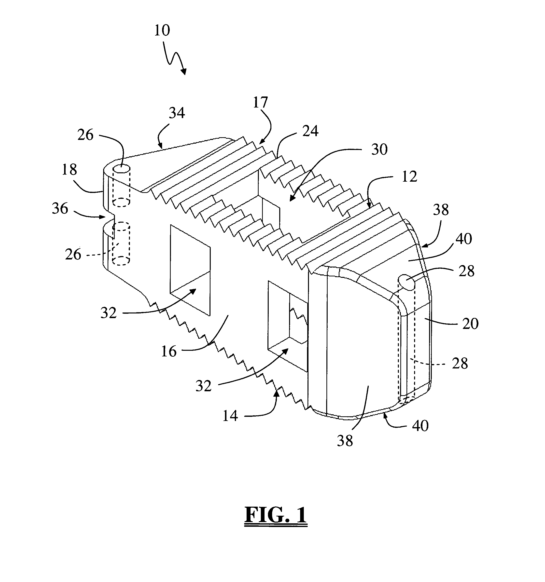
[0038]FIG. 1 illustrates a spinal fusion implant 10 according to a first broad aspect of the present invention. T...


PUM


Abstract

A spinal fusion implant of non-bone construction to be introduced into any variety of spinal target sites. The spinal fusion implant of the present invention includes a top surface, a bottom surface, first and second lateral sides, a proximal (posterior) end and a distal (anterior) end. The spinal fusion implant of the present invention may be used to provide temporary or permanent fixation within an orthopedic target site. To do so, the spinal fusion implant may be introduced into a disc space while locked to a surgical insertion instrument and thereafter employed in the proper orientation and released. Once deposited in the disc space, the spinal fusion implant of the present invention effects spinal fusion over time as the natural healing process integrates and binds the implant.

Description

CROSS REFERENCES TO RELATED APPLICATIONS[0001]The present application is a nonprovisional patent application claiming benefit under 35 U.S.C. §119(e) from U.S. Provisional Application Ser. No. 60 / 699,597, filed on Jul. 15, 2005, the entire contents of which are hereby expressly incorporated by reference into this disclosure as if set forth fully herein.BACKGROUND OF THE INVENTION[0002]I. Field of the Invention[0003]The present invention relates generally to spinal surgery and, more particularly, to a device for spinal fusion comprising a spinal fusion implant of non-bone construction to be introduced into any variety of spinal target sites.[0004]II. Discussion of the Prior Art[0005]Currently there are nearly 500,000 lumbar and cervical spinal fusion procedures performed each year in the United States. One of the causes of back pain and disability derives from the rupture or degeneration of one or more intervertebral discs in the spine. Surgical procedures are commonly performed to c...

Claims


Application Information

Patent Timeline
Patent Type & Authority Patents(United States)
IPC IPC(8): A61F2/44
CPCA61F2/4455A61F2/28A61F2002/2817A61F2002/2835A61F2002/3008A61F2002/30616A61F2002/30785A61F2002/30841A61F2002/30892A61F2002/4475A61F2002/448A61F2250/0098A61F2310/00179A61F2002/30593A61F2/46
Inventor TOHMEH, ANTOINE G.
Owner NUVASIVE
Why Eureka
Try Eureka