Microfluidic device and methods for construction and application

a microfluidic device and microfluidic duct technology, applied in microstructural technology, microtechnology, nanotechnology, etc., can solve the problems of hampered sterilisation of microfluidic ducts, hampered maintenance of inert atmosphere in microfluidic ducts, and known devices and methods for fluid manipulation in miniaturised tubes, etc., and achieve the effect of considerable precision

Inactive Publication Date: 2006-05-25
Q CHIP
View PDF48 Cites 173 Cited by
  • Summary
  • Abstract
  • Description
  • Claims
  • Application Information

AI Technical Summary

Benefits of technology

[0051] It will be apparent to those skilled in the art, given the benefit of this disclosure, that duct geometries may be designed to provide precision control of mass-transfer and by which means assume accurate control of quantum dot nucleation conditions. Quantum dots are nano-scale crystalline structures which can transform the colour of light and have numerous applications ranging from computing, photonic and materials coating to biotechnology. The energy states of the dots can be largely controlled by the size of the dot. Typically, this is achieved by introducing a desired organometallic precursor into heated triocytlphosphine oxide (TOPO) that has been vigorously stirred under an inert atmosphere. As nucleation proceeds to further shell growth the solution changes through different colour regimes as the dot size increases. Precision control of quantum dot formation has been difficult to refine because it is not readily possible to achieve ‘snap’ control of nucleation thermal and other conditions. Subsequently, quantum dots are usually sized post-synthesis to obtain particles of specific character. Quantum dot formation in the device described offers a step-change advantage where thermal control may be exercised with considerable precision. In particular, with segmented flow the mass transfer can be almost instantaneously directed by switching between vortex flow and laminar flow, the latter in an expansion zone of the duct(s). In addition the fluoropolymer construction of the device allows the reaction to be conducted at sufficiently high temperatures, which would not be possible were it constructed from other polymers (e.g. polycarbonate), and the enclosed nature of the ducts can be utilised to control the required inert atmosphere conditions. The processing can be further elaborated by the introduction of further reagents through tributary ducts to the main duct carrying the segmented flow stream, for instance to alter the composition of subsequent layers around the core of the quantum dot.

Problems solved by technology

Nevertheless, known devices and methods for the manipulation of fluids in miniaturised tubes, ducts and vessels have not met all the requirements of industry.
For example, sterilisation of, and the maintenance of an inert atmosphere in, microfluidic ducts remains a problem hampered by the materials from which many devices have been constructed.
Additionally, the use of highly corrosive fluids and high temperatures again requires very strict attention to the materials from which devices are fabricated, which, in turn, has serious implication for mass-manufacture of such devices and assemblies of such.
Glass-based substrates have been successfully manufactured, but limited, to some extent, by the complexity of 3-dimensional geometry that is cost-effectively feasible.
Also, external fluidic interconnect solutions remain crude.
Photostructurable glasses (e.g. Fotoran made by Schoot) are very expensive, sometimes 200× the cost of polymer substrates, and require several expensive and hazardous processing steps (e.g. use of HF) and specialised equipment (e.g. quartz based optics for lithography).
Stainless steel chips can be manufactured but are limited with respect to 3-dimensional geometries attainable and the surface quality possible, even with MicroElectroDischarge Machining, is frequently of insufficient resolution for microfluidic applications.
The technique suffers from high unit-cost production and very limited availability of high resolution machining tools.
However, silicon is relatively expensive for mass fabrication of relatively large-format chips which may sometimes have a short-lifespan.
In addition, with exceptions, interconnect solutions remain inelegant and low-pressure and silicon denies the use of high field strength electric fields for the generation of electro-kinetic flow and certain molecular purification processes.
Many polymers (e.g. polysulphone, polycarbonate, polymethylmethacrylate) have been utilized for the fabrication of microreactors but most have been unsuitable for use with very aggressive liquids such as acids (e.g. nitric acid) and solvents (e.g. acetonitrile).
In addition, the presence of certain substances incorporated into the polymer matrix, such as plasticisers, may cause contamination during usage, as those compounds leach from the substrate matrix into the fluids within the ducts on the chip.
However PTFE and related variants are less easily micromachined to provide fluidic ducts of micron sized dimensions and very difficult to join with itself to form enclosed microreactor ducts.
This methodology has not met all the needs of industry.
For example, such device configurations are frequently only stable for a narrow range of absolute flow rate conditions and relative flow rates of the immiscible phase liquids.
In particular, it can be difficult to control the generation of segmented flow streams with equal volumes of the immiscible phases, especially at low flow rates required by many applications.
Because the volumes of liquids are usually very small it is frequently difficult to meet the exacting requirements of industry and solutions to date are generally insufficient to meet all needs.
Furthermore, notwithstanding that devices and methods currently available for the controlled volumemetric elution of liquids, do not meet current needs, the subsequent manipulation of small liquid volumes also requires improvements.

Method used


Image

  • Microfluidic device and methods for construction and application
  • Microfluidic device and methods for construction and application
  • Microfluidic device and methods for construction and application

Examples


Embodiment Construction

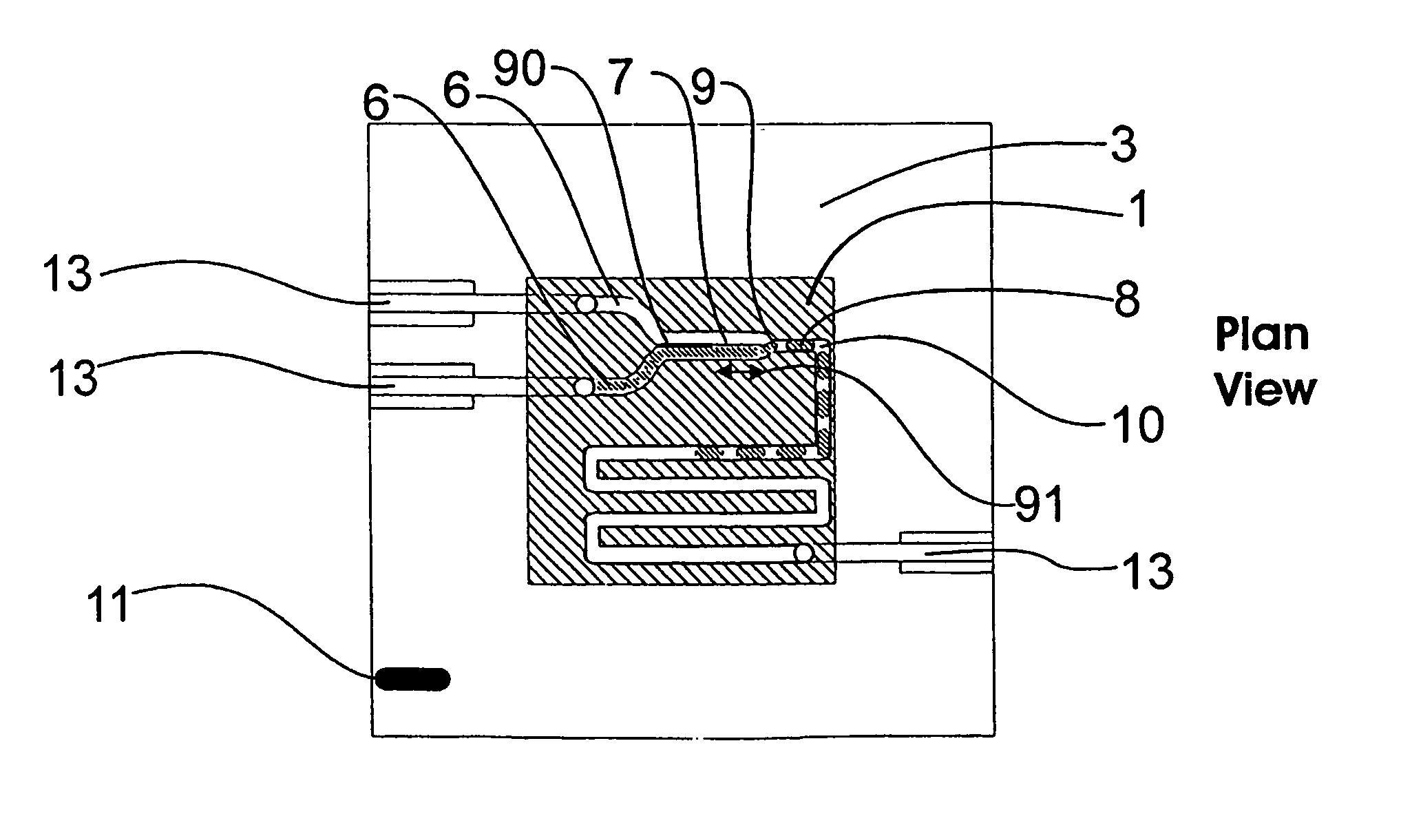
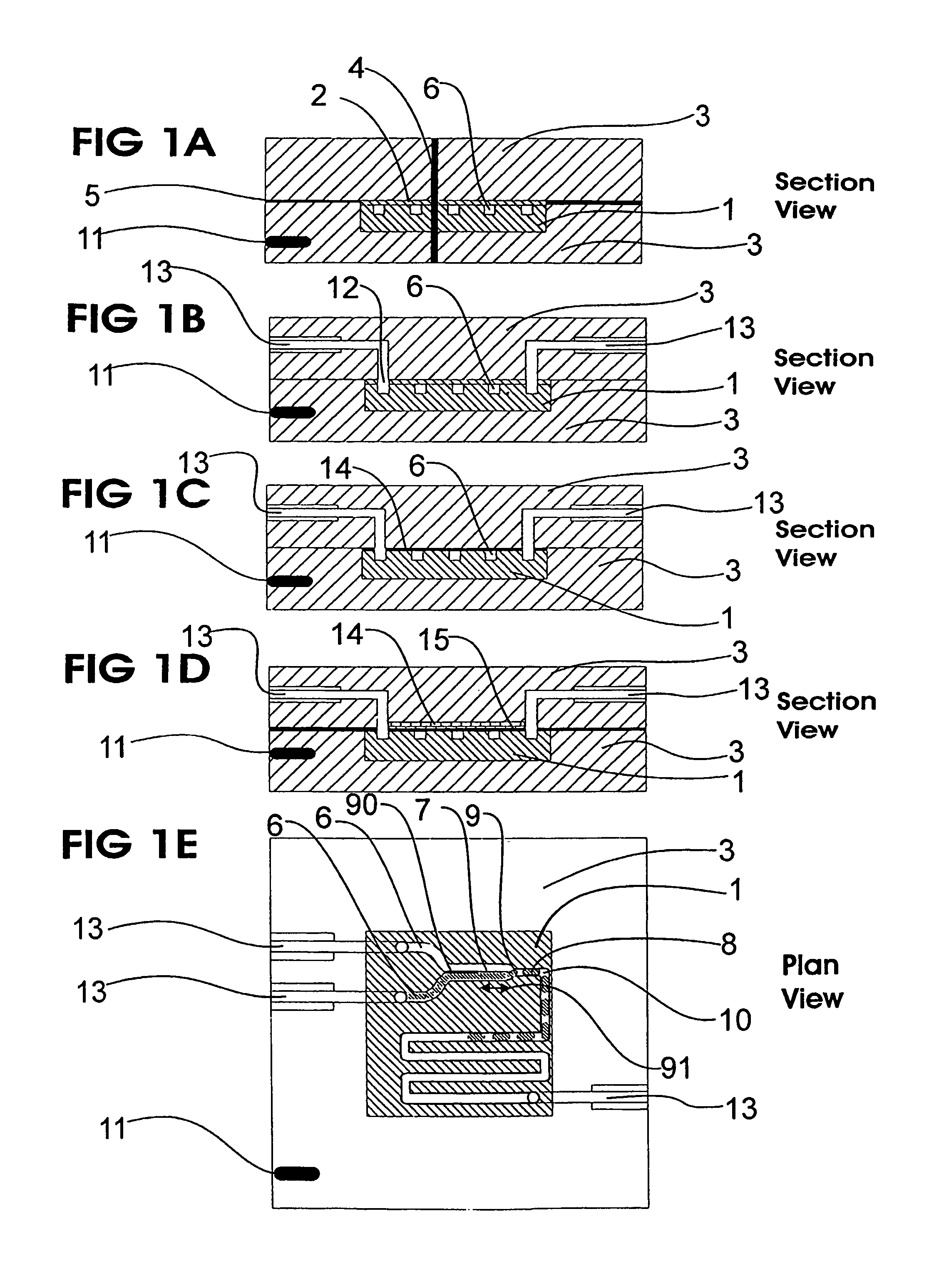
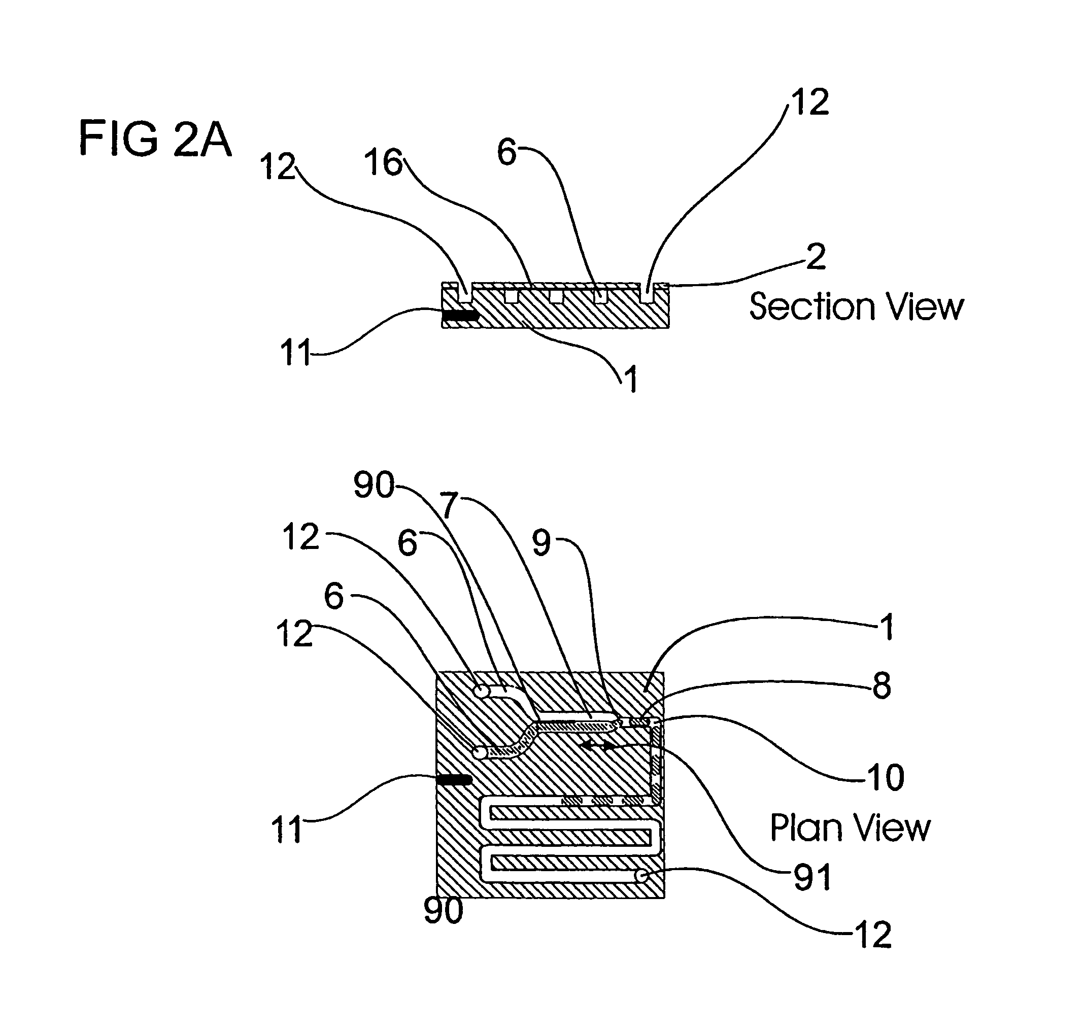
[0073]FIGS. 1A-1E show various configurations for a fluid manipulation device. In FIGS. 1A-1B a first fluoropolymer-based or -coated substrate 1 and a second fluoropolymer-based or -coated substrate 2 are held in intimate juxtaposition by various means. In FIGS. 1A-1E the substrates are encased within two or more additional layers of casement material 3. The substrate layers sit within a cavity machined within the casement layers, the depth of which is slightly shorter than the combined thickness of the substrate layers. The casement material may extend, as projections 4, through vias in the substrate layers joining compatible protrusions on another corresponding casement layer. The casement material is a thermoplastic polymer welded together by thermocompression bonding or by inductive heating, of an optional thin metallic film 5 that may be applied to one of the two layers, to >Tg+5° C. of the thermoplastic polymer. At the points where the casement materials meet, the surface may ...


PUM


Abstract

A microfluidic device comprises first and second inlet passages (13) for respective immiscible fluids, these inlet passages merging into a third passage (8) along which the two fluids flow under parallel laminar flow conditions, the third passage being formed with a constriction or other discontinuity (9) causing the two fluids to form into a flow of alternate segments.

Description

FIELD OF INVENTION [0001] The present invention relates to microfluidic devices and assemblies, methods for their construction with preferred embodiments and methodologies for the functional operation of such. BACKGROUND [0002] The miniaturisation of chemical processes onto chip-based platforms enables a plethora of novel industrial applications of existing and new chemistry, biochemistry, biomolecular science and particle science in both analysis, synthesis, assembly, decision making and computing. For example, molecular synthesis in micron-scale reactors benefits from (i) fast reaction kinetics, and (ii) high specific-areas which facilitates greater control of and / or the use of highly exothermic reactions. Many advances in so-called, microfluidics have been made in recent years. Nevertheless, known devices and methods for the manipulation of fluids in miniaturised tubes, ducts and vessels have not met all the requirements of industry. For example, sterilisation of, and the mainten...

Claims


Application Information

Patent Timeline
Patent Type & Authority Applications(United States)
IPC IPC(8): F15B21/00B01F13/00B01L3/00
CPCB01F13/0071B01L3/502784B01L2200/0636B01L2200/0673B01L2300/0864B01L2300/0867B01L2300/087B01L2300/0883B01L2300/0887B01L2400/0409B01L2400/0415B01L2400/0427B01L2400/0487B82Y10/00B82Y30/00Y10T137/2076Y10T137/2224Y10T137/8593B01F33/3021B01J19/0093B81C1/00
Inventor BARROW, DAVID ANTHONYHARRIES, NICOLAJONES, TYRONE GWYNBOURIS, KOSTAS
Owner Q CHIP
Why Eureka
Try Eureka