Process and a device for the machining of panels

a technology for machining and panels, applied in the direction of manufacturing tools, efficient propulsion technologies, final product manufacturing, etc., can solve the problems of not being able to achieve high-precision machining and ensuring adequate rigid securing, so as to avoid drag on the panel and broad freedom of action

Active Publication Date: 2010-03-23
AIRBUS OPERATIONS (SAS) +1
View PDF21 Cites 50 Cited by
  • Summary
  • Abstract
  • Description
  • Claims
  • Application Information

AI Technical Summary

Benefits of technology

[0014]Advantageously, the coordinated movement of the machining tool in operation and of the retention element, allows one to achieve continuous machining of the panel over an extended area greater than the working area of the tool, with considerable precision.
[0068]Thus, it is possible to envisage a certain number of such removable frames, allowing optimal use of the device. Likewise, it is possible to envisage different types of frames to match the different forms of panels that are liable to be machined on the device of the invention.

Problems solved by technology

Another disadvantage of machining by electro-erosion concerns the impossibility, with this process, of effecting a machining process involving different areas of depth in a single operation.
It appears however that although such a device actually allowed one to effect machining by the removal of materials from panels with non-developable warped or complex shapes, it could not be used to perform high-precision machining, particularly because of its inability to guarantee adequately rigid securing of the panel to be machined.

Method used


Image

  • Process and a device for the machining of panels
  • Process and a device for the machining of panels
  • Process and a device for the machining of panels

Examples


Embodiment Construction

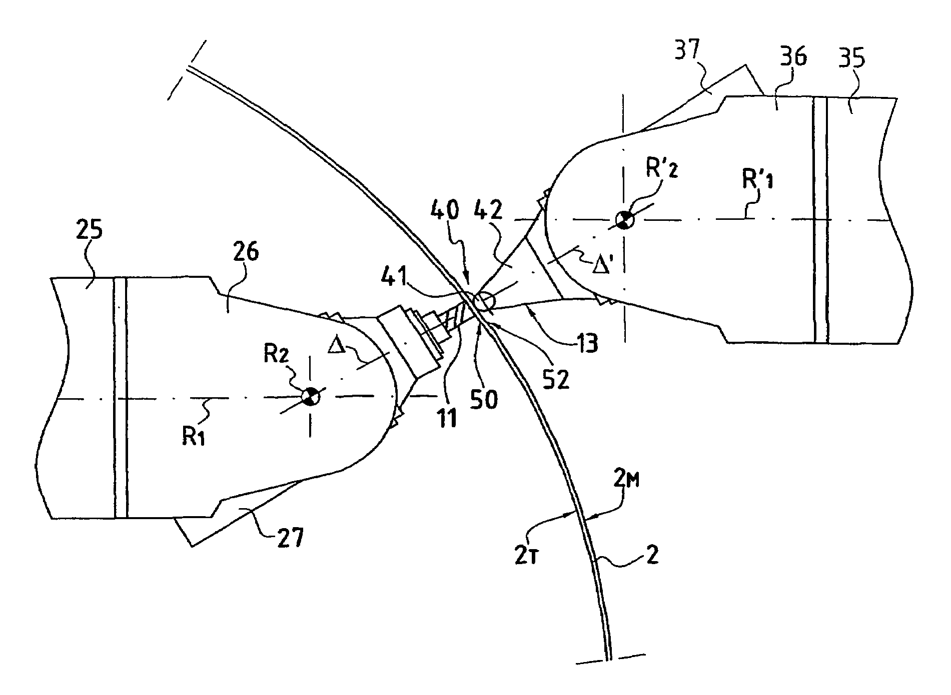
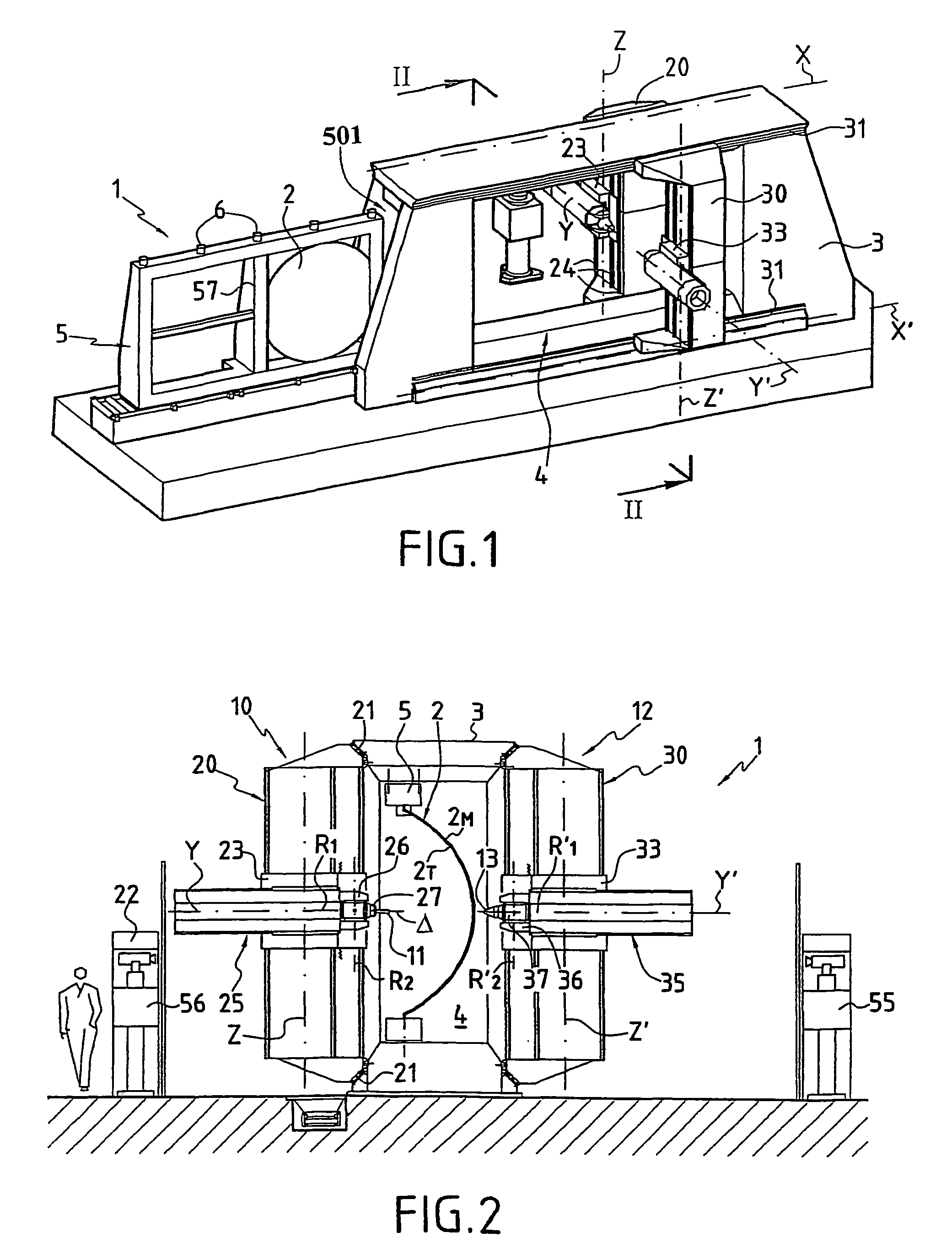
[0078]A machining device of the invention, as illustrated in FIG. 1 and designated as a whole by reference 1, allows the machining of a panel 2 that is liable to have a generally complex and non-developable shape, such as, convex or concave for example, or again locally convex and locally concave.

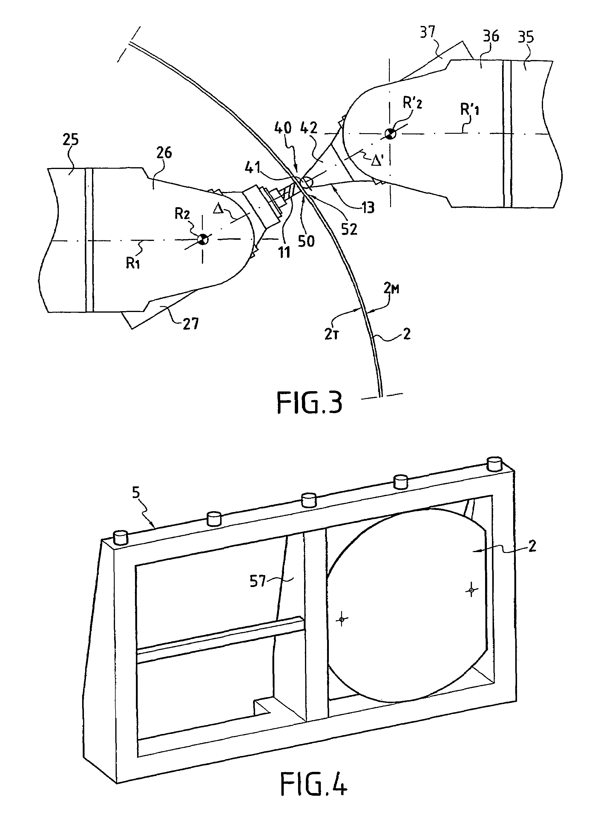
[0079]In order to perform this machining process, the device 1 includes a chassis 3 which, according to the illustrated example, is made in the form of a sort of portico that is more or less vertical, defining a window 4 inside which the panel to be machined is positioned, being held there by support resources 5. According to the illustrated example, the support resources 5 are made in the form of a removable frame that is capable of being immobilised in the window 4 on the chassis 3 by means of locking resources 6 that can be provided in any appropriate manner.

[0080]According to an essential characteristic of the invention, the machining device 1 also includes movement resources 10 for at ...


PUM

PropertyMeasurementUnit
support forceaaaaaaaaaa
forceaaaaaaaaaa
degrees of freedomaaaaaaaaaa

Abstract

A machining tool for machining a panel is arranged in a working area of a machining surface of the panel. A holding element is arranged in a support area located on a holding surface of the panel, opposing the machining surface and on an opposite side in relation to the panel to the working area. The operating machining tool and the holding element are displaced on the panel in a co-coordinated manner according to movement presenting at least one component tangentially to the surface of the panel in such a way as to maintain the opposition of the support area and the working area during the displacement of the tool in order to machine at least a part of the machining surface.

Description

FIELD OF THE INVENTION[0001]The invention concerns the technical area of devices and processes used for the machining of pre-shaped blanks or of panels, such as, for example, the panels used to manufacture aircraft cabins or fuselages.BACKGROUND OF THE INVENTION[0002]In the aforementioned area, we are familiar with the process of machining pre-shaped panels by electro-erosion to non-developable shapes. Such machining involves masking of the zones that are not to be treated, and then immersion in baths of electrolytic solutions. Thus, effectively, this process allows a localised machining of panels of general non-developable shape, but nevertheless has two major drawbacks.[0003]To begin with, machining by electro-erosion constitutes a significant source of discharges to be processed, to the extent that firstly it is necessary at the end of the machining process to clean the panels by removal of the masking elements and then rinsing followed by recycling of the cleaning solutions as w...

Claims


Application Information

Patent Timeline
Patent Type & Authority Patents(United States)
IPC IPC(8): B23C3/13B23C3/16B21J15/10B23Q1/01B23Q1/48B23Q1/54B23Q1/62B23Q1/76B64F5/00
CPCB23Q1/01B23Q1/488B23Q1/5412B23Q1/626B23Q1/766B64F5/0009B23Q1/4857Y10T409/308512Y02T50/90Y10T409/303808Y10T409/30756Y10T409/303752Y10T409/309744Y10T409/307896Y10T409/30868B64F5/10Y02P70/50
Inventor PANCZUK, RENEFOISSAC, PIERRE-YVES
Owner AIRBUS OPERATIONS (SAS)
Why Eureka
Try Eureka