Motor stator structure

a technology of motor stator and stator body, which is applied in the direction of dynamo-electric machines, magnetic circuit shapes/forms/constructions, supports/enclosements/casings, etc., can solve the problems of high cost and difficult fabrication, and achieve the effect of reducing fabrication cost, reducing manufacturing costs, and considerable precision

Inactive Publication Date: 2009-08-06
CHENG CHANG MACHINE ELECTRONIC CORP
View PDF6 Cites 5 Cited by
  • Summary
  • Abstract
  • Description
  • Claims
  • Application Information

AI Technical Summary

Benefits of technology

[0004]The primary objective of the present invention is to provide an easy-to-fabricate and cost-efficient motor stator structure having a considerable precision.
[0005]To achieve the abovementioned objective, the present invention proposes an improved motor stator structure, which comprises: a plurality of silicon steel plates, two rotor bearing blocks, and a plurality of pins. The silicon steel plates have a plurality of through-holes along the rims thereof and are assembled together to form a stack. The two rotor bearing blocks are respectively arranged at two side of the stack of the silicon steel plates and have buried holes corresponding to the through-holes of the silicon steel plates. The pins have an identical length. The pins have a diameter exactly identical to that of the through-holes of the silicon steel plates so that the pins can tightly fit the through-holes of the silicon steel plates. Thus, the pins are forced to pass through the silicon steel plates to make all the silicon steel plates neatly and concentrically arranged. Then, the pins are inserted into the buried holes to closely contact the rotor bearing blocks.
[0006]The present invention uses the pins to tightly secure the silicon steel plates and the rotor bearing blocks so that they can be concentrically assembled. As all the pins, which closely contact the rotor bearing blocks, have an identical length, the two rotor bearing blocks are parallel to each other and vertical to the stacking direction of the silicon steel plates. Compared with the conventional technologies, the present invention is an easy-to-fabricate motor stator structure, which has a lower fabrication cost and can satisfy users.

Problems solved by technology

Such a process needs a special fixture and a large-size lathe, which results in fabrication difficulties and a high cost.

Method used


Image

  • Motor stator structure
  • Motor stator structure
  • Motor stator structure

Examples


Embodiment Construction

[0011]Below, the preferred embodiments are described in cooperation with the drawings to make easily understand the objectives, characteristics, and efficacies of the present invention.

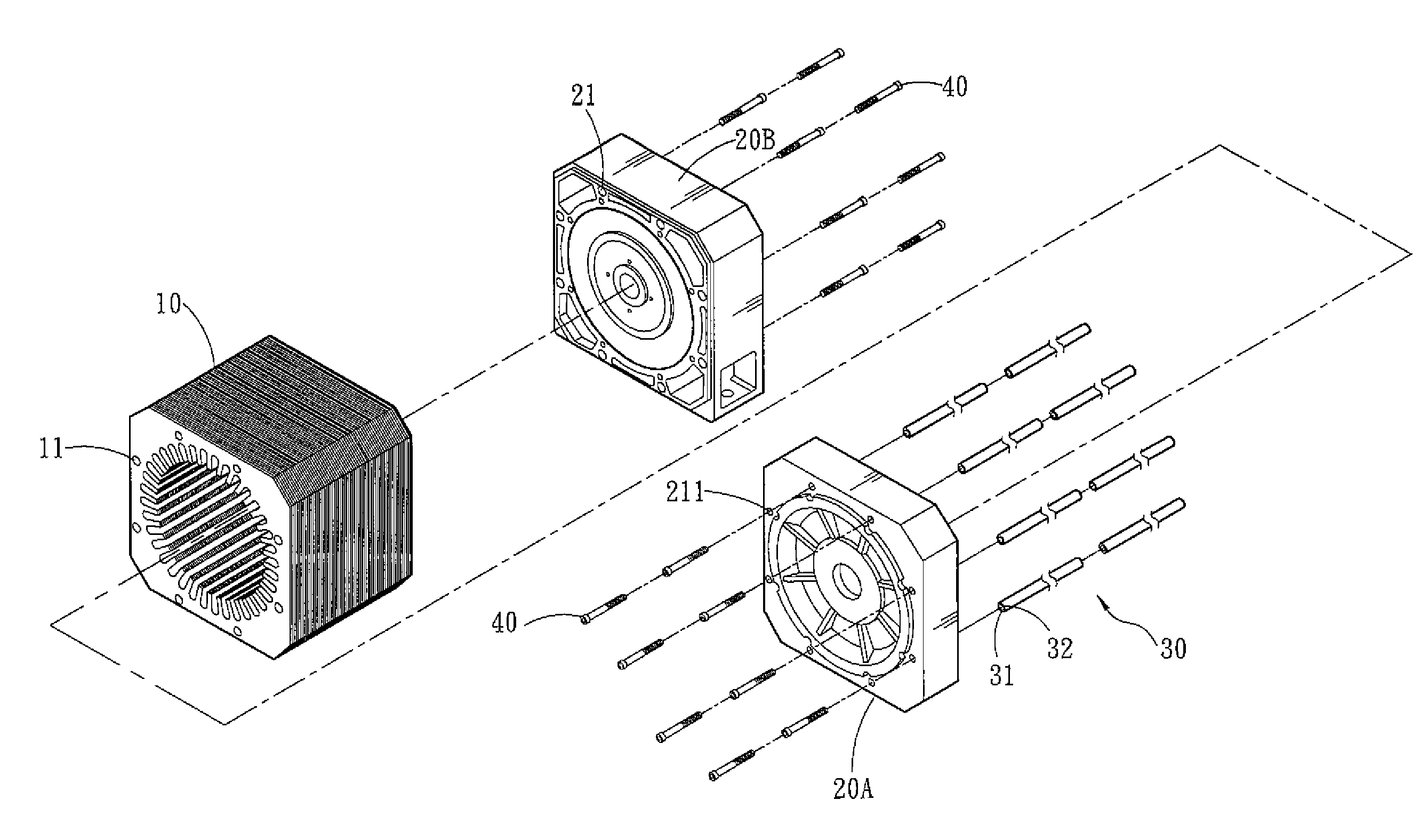
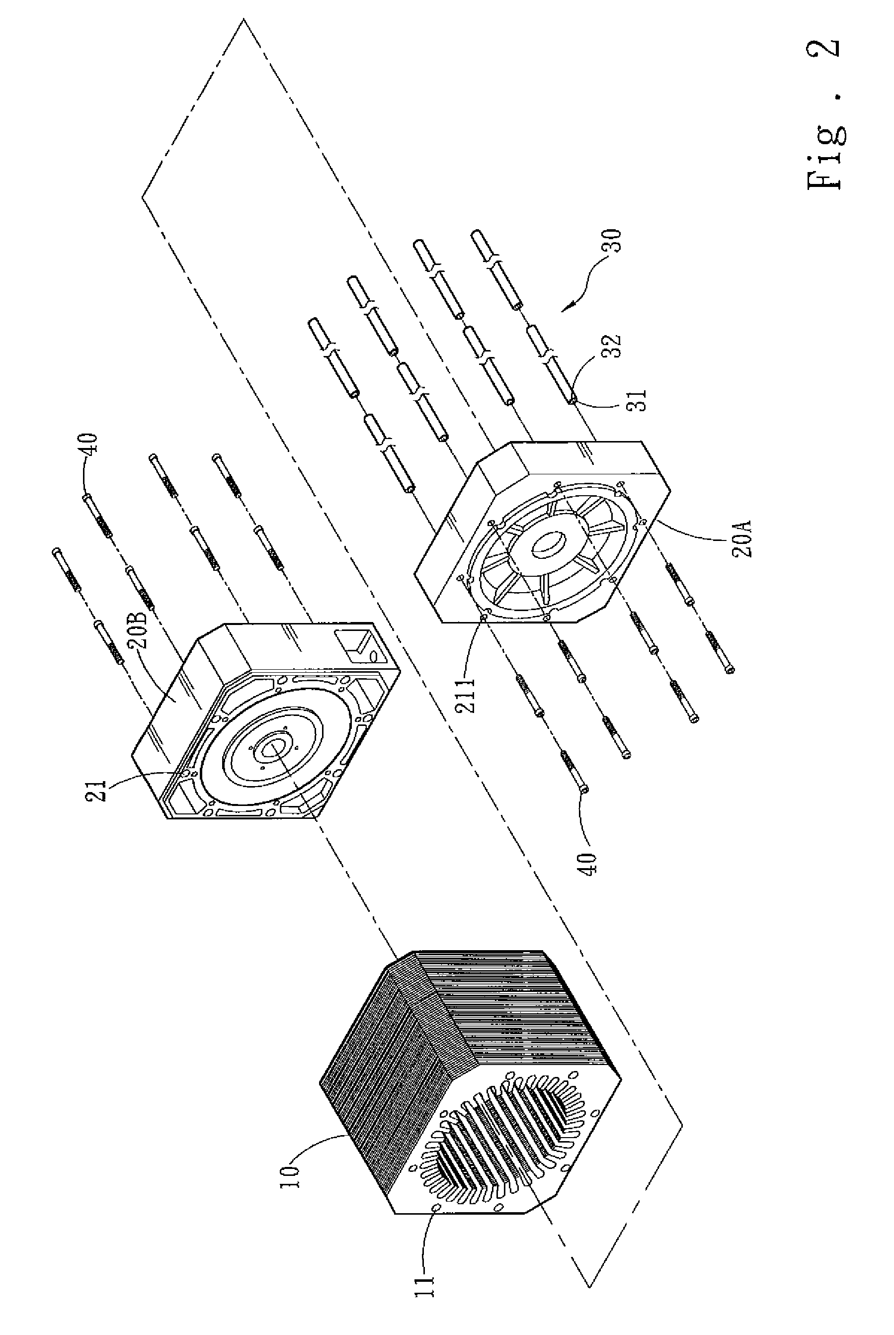
[0012]Refer to FIG. 2 and FIG. 3. The present invention comprises: a plurality of silicon steel plates 10, two rotor bearing blocks 20A and 20B, and a plurality of pins 30. The silicon steel plate 10 has a plurality of through-holes 11 along the rim thereof, and the through-holes 11 are uniformly distributed. The number of the through-holes 11 is determined by the customer. In the drawings, the silicon steel plate 10 has eight through-holes 11, However, the present invention is not limited by the drawings. The silicon steel plates 10 are assembled together to form a stack, and the two rotor bearing blocks 20A and 20B are respectively arranged at two sides of the stack of the silicon steel plates 10. The rotor bearing blocks 20A and 20B have buried holes 21 corresponding to the through-holes 11 of the ...


PUM


Abstract

The present invention discloses an improved motor stator structure, which comprises: a plurality of silicon steel plates, two rotor bearing blocks, and a plurality of pins. In the present invention, the pins are forced to pass through the through-holes of the silicon steel plates and then inserted into the buried holes to make the end faces of the pins closely contact the motor rotor bearing blocks. Thereby, the silicon steel plates and the rotor bearing blocks are concentrically assembled together. As all the pins has an identical length and closely contact the rotor bearing blocks, the rotor bearing blocks are parallel to each other and vertical to the stacking direction of the silicon steel plates. Thus, the present invention is an easy-to-fabricate motor stator structure, which has a considerable precision and a lower fabrication cost.

Description

FIELD OF THE INVENTION[0001]The present invention relates to a motor stator, particularly to a motor stator structure.BACKGROUND OF THE INVENTION[0002]Refer to FIG. 1 for a conventional motor stator structure. The conventional motor stator structure comprises: a stator 1 and a rotor 2. The stability and efficiency of motor operation correlates closely with the assembly precision of the stator 1 and the rotor 2. The conventional stator 1 includes a plurality of silicon steel plates 3. The silicon steel plates 3 are clamped by two assembly boards 4A and 4B from two sides thereof and then fastened by a plurality of screws 5. The assembly boards 4A and 4B have positioning grooves 6A and 6B, which are fabricated with a machining method and used to precisely locate rotor bearing blocks 7A and 7B. Then, the rotor 1 is sleeved inside the rotor bearing blocks 7A and 7B and the stator 1. Thus is completed the assembly of the stator 1 and the rotor 2.[0003]In the conventional motor stator stru...

Claims


Application Information

Patent Timeline
Patent Type & Authority Applications(United States)
IPC IPC(8): H02K5/15H02K1/12H02K15/16H02K1/18
CPCH02K1/185H02K15/16H02K5/15
Inventor PONG, BORGAN
Owner CHENG CHANG MACHINE ELECTRONIC CORP
Why Eureka
Try Eureka