Optical mouse having an optical structure capable of high sensibility

a mouse and optical structure technology, applied in the field of optical mouse with an optical structure capable of high sensibility, can solve the problems of insufficient data for image analysis to be performed, insufficient wear of the roller, and deposition of filth inside the mouse enclosed by the roller, etc., and achieves the effects of low loss, high sensibility, and energy saving

Inactive Publication Date: 2007-09-27
CHIC TECH CORP
View PDF0 Cites 85 Cited by
  • Summary
  • Abstract
  • Description
  • Claims
  • Application Information

AI Technical Summary

Benefits of technology

[0012] It is, therefore, an object of the present invention to provide an optical mouse having an optical structure capable of high sensibility, in which a photosensor is disposed at an optimal angle of between 1 and 179 degrees or between 181 and 359 degrees where the photosensor stands at a right angle with respect to a path of a reflected version of a light beam emitted from a light source. It is to be noted that the light reflection is different as the surface of the substance contacted with the light varies and the light is always reflected along a minimum path (a chopstick seeming like broken may be an example). As such, the reflected light may be acquired with a minimum loss and the purpose of energy saving is achieved. In this manner, a cursor controlled by the optical mouse may move on a display with a considerable precision.

Problems solved by technology

As generally known, the conventional roller mouse is inherent with disadvantages of susceptibility of wear of the roller and deposition of filth inside the mouse enclosed by the roller.
However, since the photosensor does not receive the reflected light at a right angle considered as an optimal angle, the received light may have a loss, which is particularly critical when the reflected light is not sufficient in luminance, leading to insufficient data for the to-be-performed image analysis.
However, this causes a higher power cost and may not achieve the energy saving purpose.
Therefore, the photosensor may not be disposed at an optimal direction and the path of the reflected light may be caused to walk off.
As such, the photosensor may not receive the reflected light in a desired or devised manner.

Method used


Image

  • Optical mouse having an optical structure capable of high sensibility
  • Optical mouse having an optical structure capable of high sensibility
  • Optical mouse having an optical structure capable of high sensibility

Examples


Embodiment Construction

[0020] To enable the present invention to be fully understood, the present invention will be described in detail below taken from the preferred embodiments with reference to the annexed drawings.

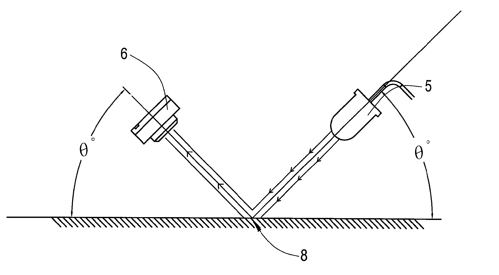
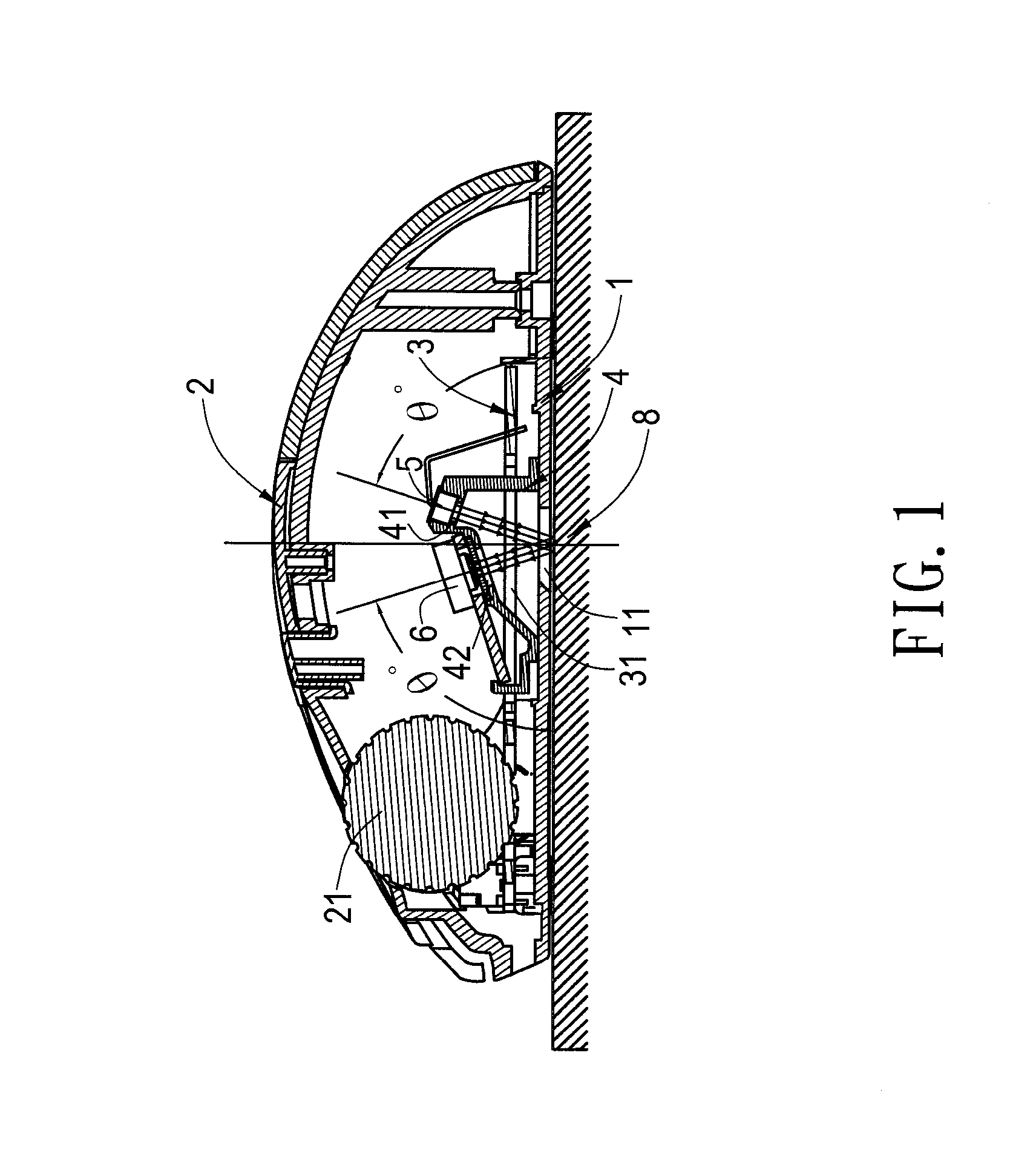
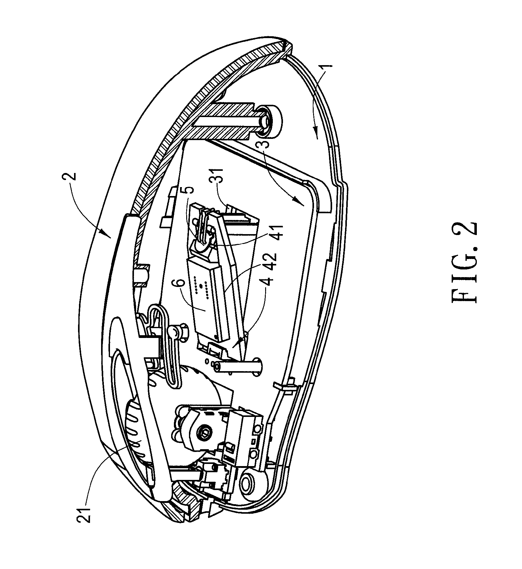
[0021] Referring first to FIG. 1, FIG. 2 and FIG. 3, an optical mouse according to the present invention may be manipulated on a target surface 8 and comprises a base 1, an upper cover 2, a circuit board 3, a support frame 4, a light source 5 and a photosensor 6. The target surface 8 may be any suitable surface such as a mouse pad surface, a desk surface, a glass surface and a plastic surface. The base 1 has a through-hole 11 at a bottom end thereof. The upper case 2 is disposed over the base 1 and has a set of control keys 2 thereon. The circuit board 3 is disposed on the base 1 and has a reception hole 31 aligned to the through-hole 11. The support frame 4 is disposed at an upper end of the circuit board 3 and connected to the base 1. Further, a first positioning hole 41 and a second posi...


PUM


Abstract

An optical structure of the optical mouse is disclosed, which comprises a light source providing an incident light beam transmitted onto a target surface at a specific incident angle and a photosensor pre-disposed at an angle of between 1 and 179 degrees or between 181 and 359 degrees so as to be aligned to stand at a right angle with respect to a path of the reflected version and thus achieve a proper acquirement of luminance and image of the reflected version of the incident light from the target surface.

Description

BACKGROUND OF THE INVENTION [0001] 1. Field of the Invention [0002] The present invention pertains to an optical mouse having an optical structure capable of high sensibility. Particularly, the present invention pertains to an optical mouse having an optical structure capable of high sensibility, in which a photosensor is disposed at an angle of between 1 to 179 degrees or between 181 and 359 degrees so as to be aligned to stand at a right angle with respect to a path of a reflected light to achieve a proper acquirement of luminance of the reflected light. [0003] 2. Description of the Prior Art [0004] Mouse is an indispensable peripheral device to a computer since it can supercede a keyboard, having a much bigger volume as compared thereto, in inputting to the computer due to the superior manipulativeness, particularly for use in manipulation of web pages and multi-media. Form of the mouse has advanced from a roller mouse form used in the past to an optical mouse form used today. As...

Claims


Application Information

Patent Timeline
Patent Type & Authority Applications(United States)
IPC IPC(8): G09G5/08
CPCG06F3/03543
Inventor WU, CHUN-CHEPENG, CHUN-CHING
Owner CHIC TECH CORP
Why Eureka
Try Eureka