Touch switch for electrical appliances and electrical appliance provided with such switch

a technology of touch switch and electrical appliance, which is applied in the direction of electronic switching, electrical apparatus, pulse technique, etc., can solve the problems of increasing physical dimensions, increasing and reducing the overall cost of the control panel

Inactive Publication Date: 2009-04-09
WHIRLPOOL CORP
View PDF6 Cites 67 Cited by
  • Summary
  • Abstract
  • Description
  • Claims
  • Application Information

AI Technical Summary

Benefits of technology

[0021]According to the present invention, no leg is needed to cover the gap between touch area and sensor surface due to light source or display package.
[0022]Moreover the

Problems solved by technology

The use of opaque walls increases physical dimensions and renders the mounting quite complex.
Electrodes can also be made of transparent conductive material (such as indium tin oxide), located between the light guide and the lower surface of the transparent cover under which the touch switch is placed, with an increase of the overall cost of the control panel.
Up to now, for assuring such mechanical contact

Method used


Image

  • Touch switch for electrical appliances and electrical appliance provided with such switch
  • Touch switch for electrical appliances and electrical appliance provided with such switch
  • Touch switch for electrical appliances and electrical appliance provided with such switch

Examples


Embodiment Construction

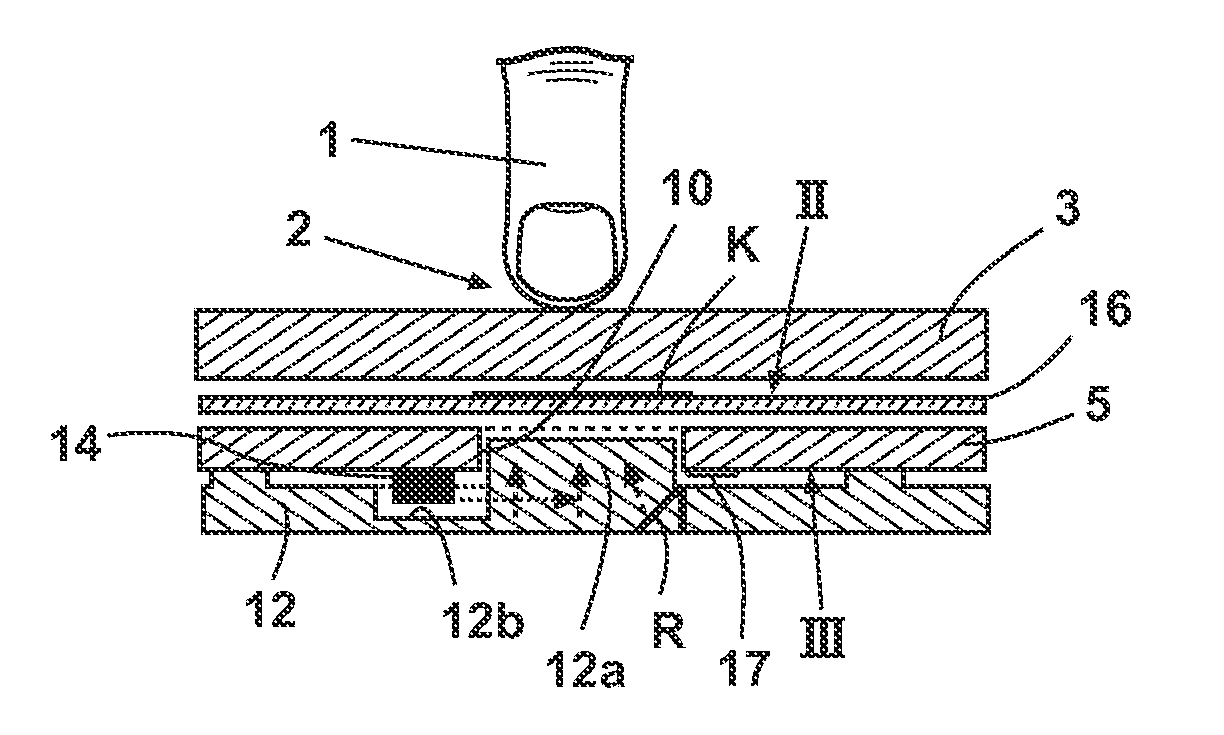
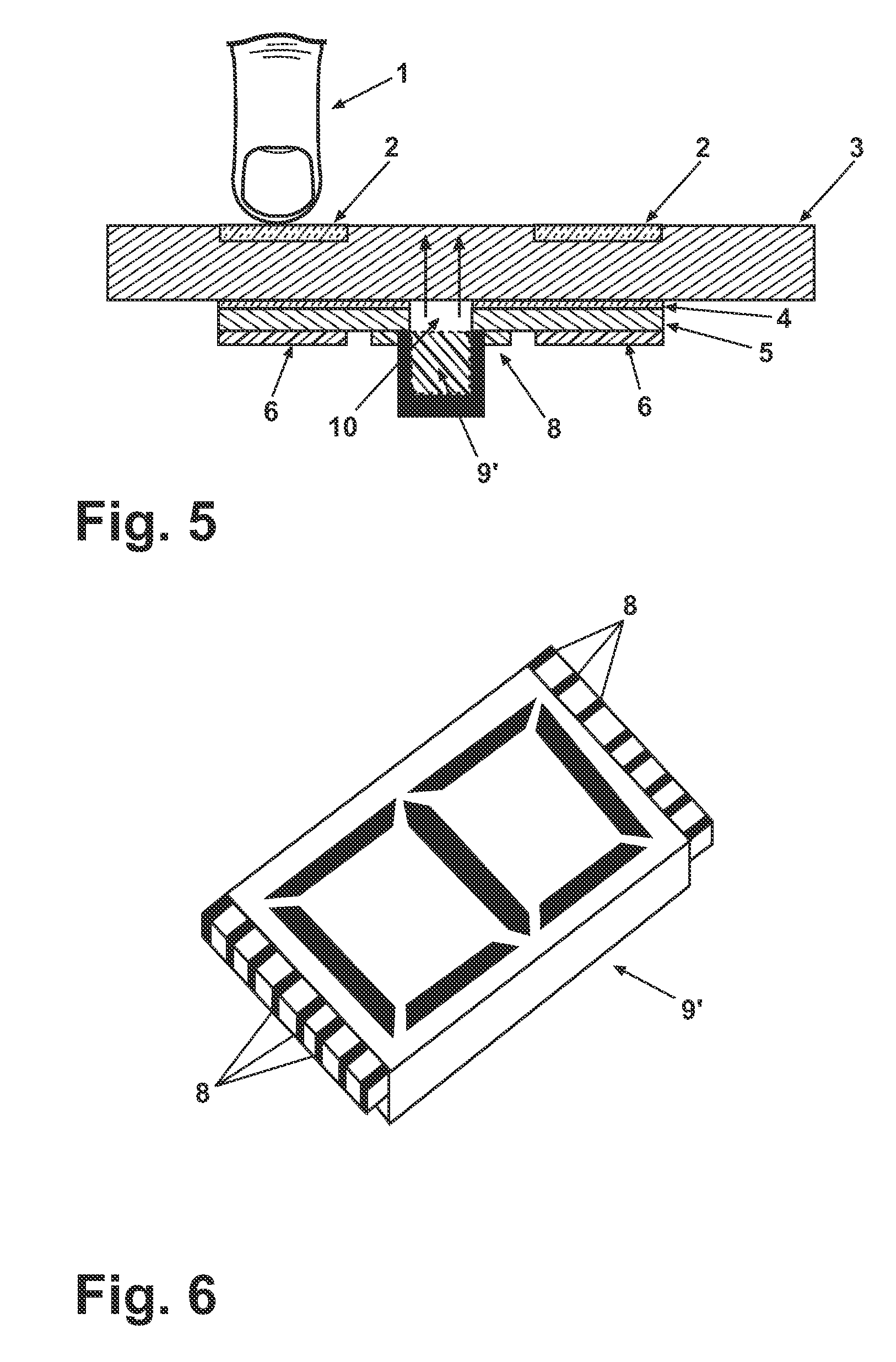
[0032]With reference to the drawings, a touch switch presents a non-conductive transparent cover 3, for instance of glass or polymeric material. On the transparent cover 3 there is at least one touch sensitive area 2 adapted to be touched by the user's finger 1.

[0033]On the lower face of the transparent cover 3, a single side printed circuit board (PCB) 5 is attached by means of a non-conductive transparent adhesive 4 (figure 5). The PCB 5 is provided with a cut-out 10.

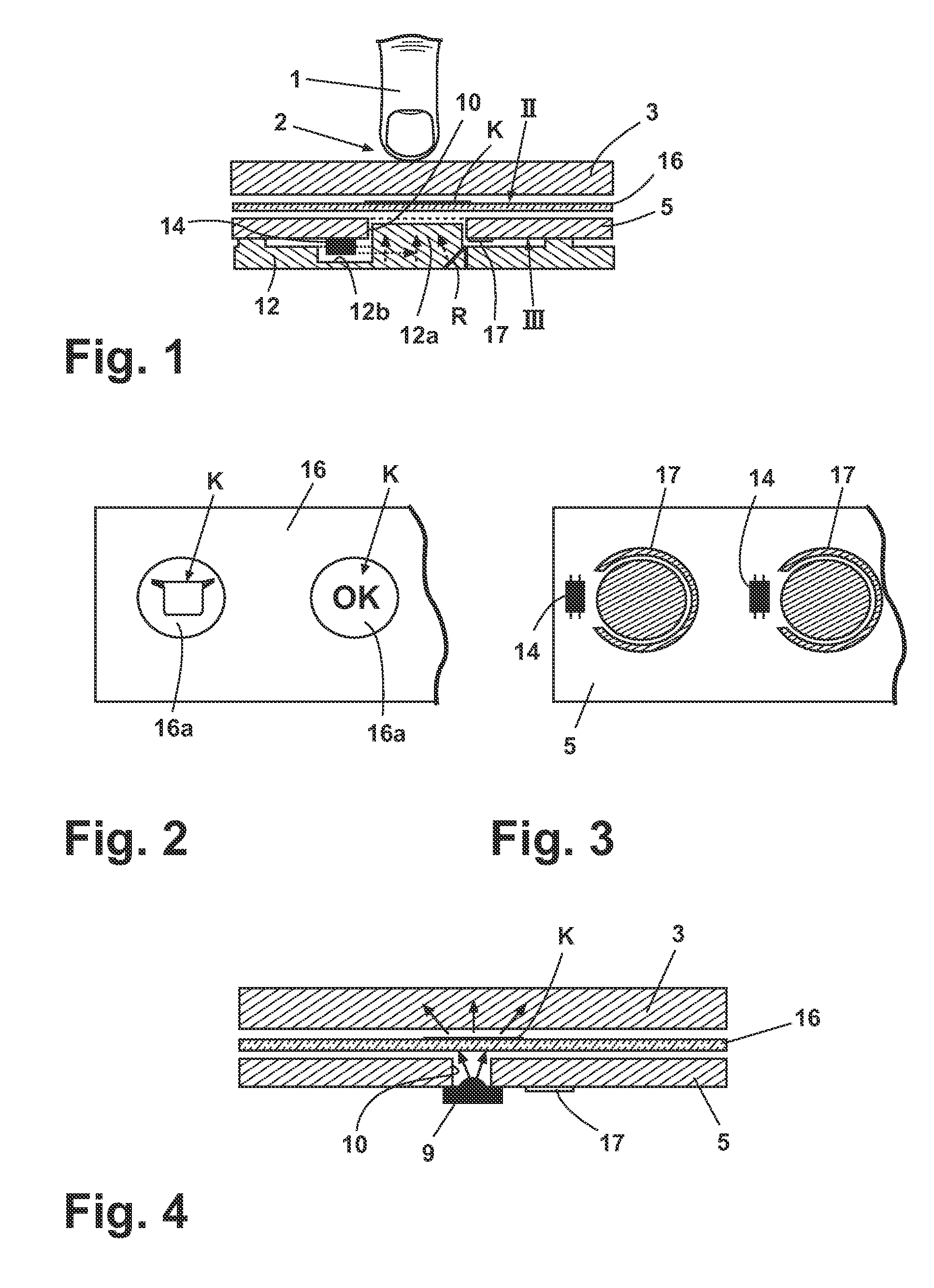
[0034]With reference to FIG. 1, on the side of the PCB 5 opposite the transparent cover 3 (i.e. the side with the metallic tracks), there is provided a plastic light guide 12 in the form of a planar sheet provided with a protrusion 12a located in the cut-out 10 of the PCB. The light guide 12 is fixed to the PCB 5 by means of adhesive or the like, and adjacent the protrusion 12a the light guide 12 presents a seat 12b in which a LED 14, electrically connected to and supported by the PCB 5, is placed. In the area surroun...


PUM


Abstract

A touch switch for an electrical appliance having a capacitive flat electrode, a light source, a transparent cover and a printed circuit board connected to the electrode is disclosed. The light source is mounted on a face of the printed circuit board opposite the transparent cover and the printed circuit board presents a cut-out for allowing light transmission from the light source towards the transparent cover.

Description

BACKGROUND OF THE INVENTION[0001]1. Field of the Invention[0002]The present invention relates to a touch switch for an electrical appliance to be used on control panels thereof. The invention also refers to a capacitive touch switch comprising a capacitive flat sensor surface, a light source, a transparent cover provided over said touch switch and a printed circuit board connected to the capacitive sensor element.[0003]2. Description of the Related Art[0004]With the term “switch” we mean every kind of touch sensors which usually replace the traditional buttons in modern flush user interfaces.[0005]Visual feedback activation of a touch switch control is simply provided by a light source, for example a light emitting diode (LED). Usually several touch switches are arranged, together with control board thereof, in a control panel.[0006]To avoid optical interference between adjacent touch switches, light flux shall be conveyed from a light source to the related touch sensitive switch su...

Claims


Application Information

Patent Timeline
IPC IPC(8): H01H9/00
CPCH03K17/962H03K2217/96076H03K2217/96079H03K2217/960755
Inventor ARIONE, ETTOREARENA, GIUSEPPELAZZAROTTO, ROBERTOBRAGHINI, GIORGIO
Owner WHIRLPOOL CORP
Why Eureka
Try Eureka