Collimating optical device and system

a collimating optical and lightguide technology, applied in the direction of polarising elements, planar/plate-like light guides, instruments, etc., can solve the problems of inconvenient installation and at times even unsafe use, high cost where high-performance is required, and facilitate the design and fabrication of compact imaging devices. , the effect of easy incorporation

Active Publication Date: 2010-08-12
LUMUS LTD
View PDF11 Cites 107 Cited by
  • Summary
  • Abstract
  • Description
  • Claims
  • Application Information

AI Technical Summary

Benefits of technology

[0006]The present invention facilitates the design and fabrication of a compact imaging device for, among other applications, HMDs. The invention allows for relatively wide FOVs together with relatively large EMB values. The resulting optical system offers a large, high-quality image, which also ac

Problems solved by technology

As a result, the combiner-projector HUD system is necessarily bulky, large and requires considerable installation space, which makes it inconvenient for installation and at times even unsafe to use.
The large optic

Method used


Image

  • Collimating optical device and system
  • Collimating optical device and system
  • Collimating optical device and system

Examples


Embodiment Construction

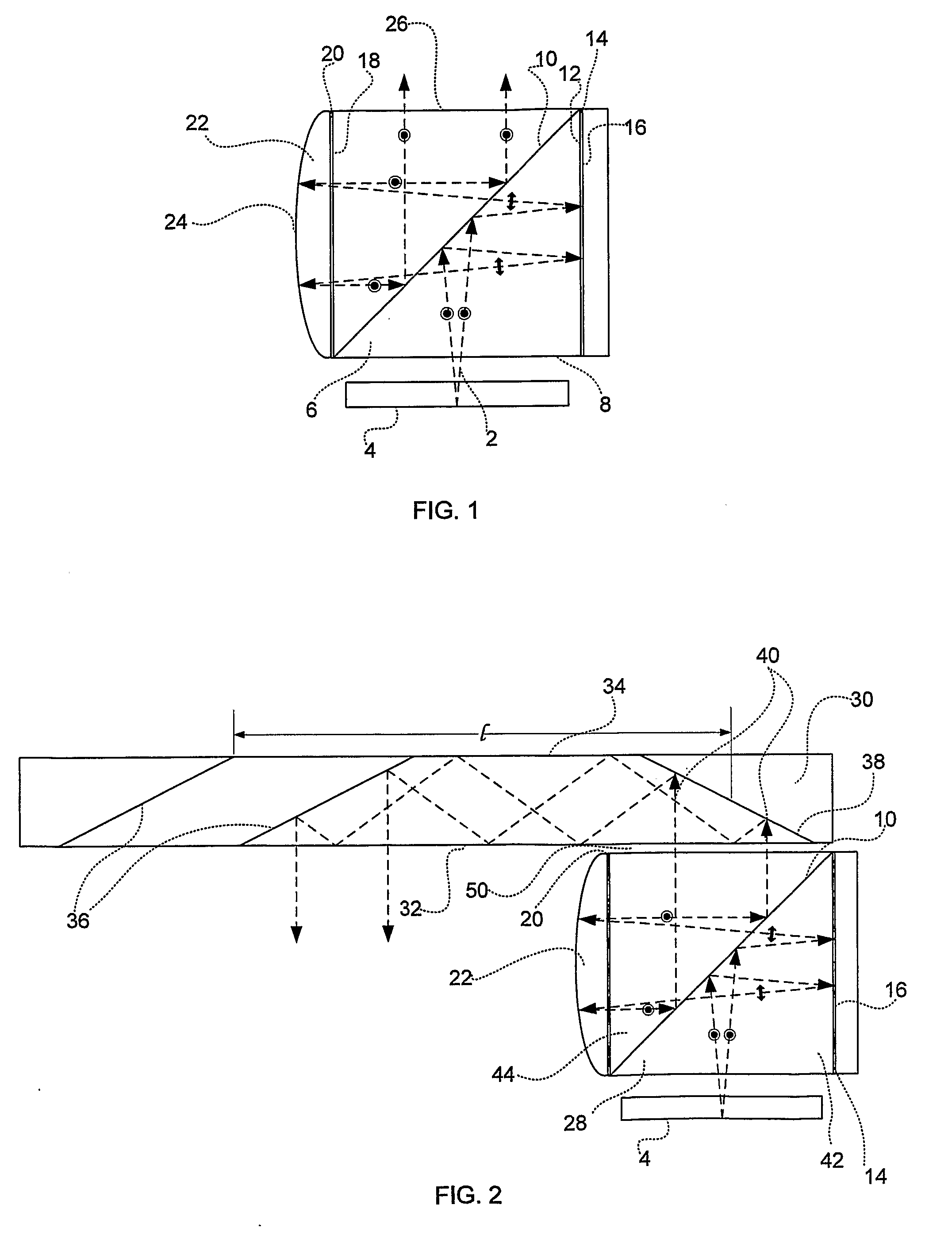
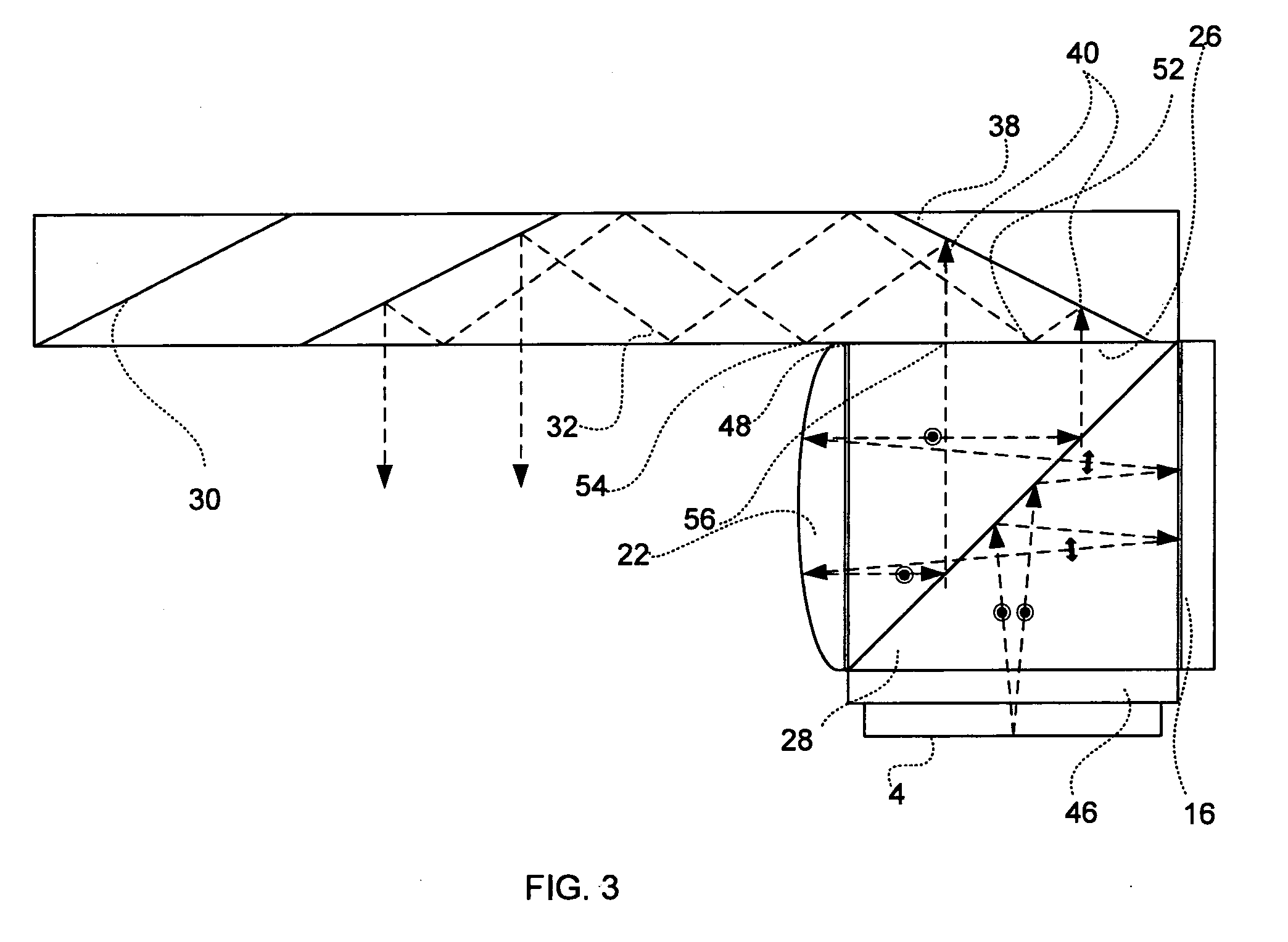
[0065]In the following there will be described superior structures of optical devices that are more compact than the prior art devices, having various configurations suitable for matching preferred outlines of optical systems, while still maintaining desired optical properties of the system. In such a structure, which exploits the fact that in most microdisplay light sources such as LCDs or LCOS light sources, the light is linearly polarized, as illustrated in FIG. 1. As shown, the s-polarized input light-waves 2 from the display light source 4 are coupled into a light-guide 6, which is usually composed of a light-waves transmitting material, through its lower surface 8. Following reflection-off of a polarizing beamsplitter 10, the light-waves are coupled-out of the substrate through a surface 12 of the light-guide 6. The light-waves then pass through a quarter-wavelength retardation plate 14, reflected by a reflecting optical element 16, e.g., a flat mirror, return to pass again th...


PUM


Abstract

There is provided a light-guide, compact collimating optical device, including a light-guide having a light-waves entrance surface, a light-waves exit surface and a plurality of external surfaces, a light-waves reflecting surface carried by the light-guide at one of the external surfaces, two retardation plates carried by light-guides on a portion of the external surfaces, a light-waves polarizing beamsplitter disposed at an angle to one of the light-waves entrance or exit surfaces, and a light-waves collimating component covering a portion of one of the retardation plates. A system including the optical device and a substrate, is also provided.

Description

FIELD OF THE INVENTION[0001]The present invention relates to light-guide, compact collimating optical devices (LCCDs) and to optical systems which include one or more of these devices. The term “light-guides” refers to any light-transmitting body, preferably light-transmitting, solid bodies, also known as optical substrates.[0002]The invention can be implemented to advantage in a large number of imaging applications, such as head-mounted displays (HMDs) and head-up displays (HUDs), cellular phones, compact displays, 3-D displays, compact beam expanders, as well as non-imaging applications, such as flat-panel indicators, compact illuminators and scanners.BACKGROUND OF THE INVENTION[0003]One of the important applications for compact optical devices is in the field of HMDs, wherein an optical module serves both as a reflecting optical element and a combiner, in which a two-dimensional display is imaged to infinity and reflected into the eye of an observer. The display can be obtained d...

Claims


Application Information

Patent Timeline
IPC IPC(8): G02B27/28G02B27/30G02B30/25
CPCG02B6/00G02B6/2706G02B6/0056G02B27/0101G02B27/0172G02B27/286G02B6/34G02B27/28G02B27/26G02B27/283G02B27/30G02F1/0136G02B6/2773G02B5/3083G02B6/0035G02B5/045G02B6/272G02B6/2766G02B23/02G02B2027/0134G02B2027/0178G02B30/25G02B30/35H04N13/332H04N13/344G02B5/04G02B5/30G02B5/3066G02B5/32G02B6/003G02B27/0025G02B27/0176G02B27/1006G02B27/106G02B27/145G02B2027/011G02B2027/0116G02B2027/0123G02B2027/0125G02B2027/0132G02B2027/015
Inventor AMITAI, YAAKOVHADAD, MALIFRIEDMANN, NAAMAH
Owner LUMUS LTD
Why Eureka
Try Eureka