Atomic layer deposition system

a technology of atomic layer and deposition system, which is applied in the direction of chemical vapor deposition coating, metal material coating process, coating, etc., can solve the problems of insufficient gas flow adjustment, variance in web thickness, and inability to accommodate for variance in substrate thickness nor adjust the gas flow, etc., and achieves the effect of time or space-based gas deposition, and largely inadequate conventional ald system

Active Publication Date: 2021-05-27
CARPE DIEM TECH
View PDF6 Cites 0 Cited by
  • Summary
  • Abstract
  • Description
  • Claims
  • Application Information

AI Technical Summary

Benefits of technology

[0013]It is another object of the present invention to provide an ALD system which is uniquely designed to deposit thin layers of material onto a common substrate at relatively high speeds and with considerable precision.
[0015]It is still another object of the present invention to provide an ALD system of the type as described above which is designed to regulate temperature at the reactant site in order to ensure proper reactant deposition without damaging the substrate.

Problems solved by technology

Applicant has recognized that the fixed-sized nature of the gap between the deposition head and drum renders conventional ALD systems incapable of accommodating for variances in substrate thickness nor adjustability to tune the gas flows.
Because variances in web thickness often arise due to differences in intended applications, conventional ALD systems which separate the deposition of gas either in time or space have all been found to be largely inadequate.
However, minimum reactant temperatures may exceed the temperature tolerance of the target substrate, particularly for webs constructed of polymers with glass transition temperatures that fall below the required minimum reaction temperatures.
As a result, precursor materials utilized in atomic layer deposition are often restricted to materials which can be suitably applied at a temperature that falls beneath the temperature damage threshold for the target substrate or target substrates are restricted to those which survive the required deposition temperatures of the reactants.

Method used


Image

  • Atomic layer deposition system
  • Atomic layer deposition system
  • Atomic layer deposition system

Examples


Embodiment Construction

Atomic Layer Deposition (ALD) System 11

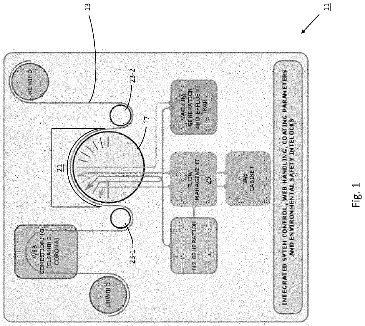
[0030]Referring now to FIG. 1, there is shown a simplified schematic representation of an atomic layer deposition (ALD) system which is constructed according to the teachings of the present invention, the ALD system being defined generally by reference numeral 11. As will be explained in detail below, system 11 is uniquely designed to deposit thin layers of precursor material onto a common substrate 13 at relatively high speeds and with considerable precision.

[0031]As defined herein, the term “substrate” denotes any surface or material which is suitable for receiving deposition layers. In the description that follows, substrate 13 is represented as an elongated web of material, thereby enabling layer deposition processes to be applied continuously at relatively high speeds. However, it is to be understood that substrate 13 could be represented in alternative forms without departing from the spirit of the present invention.

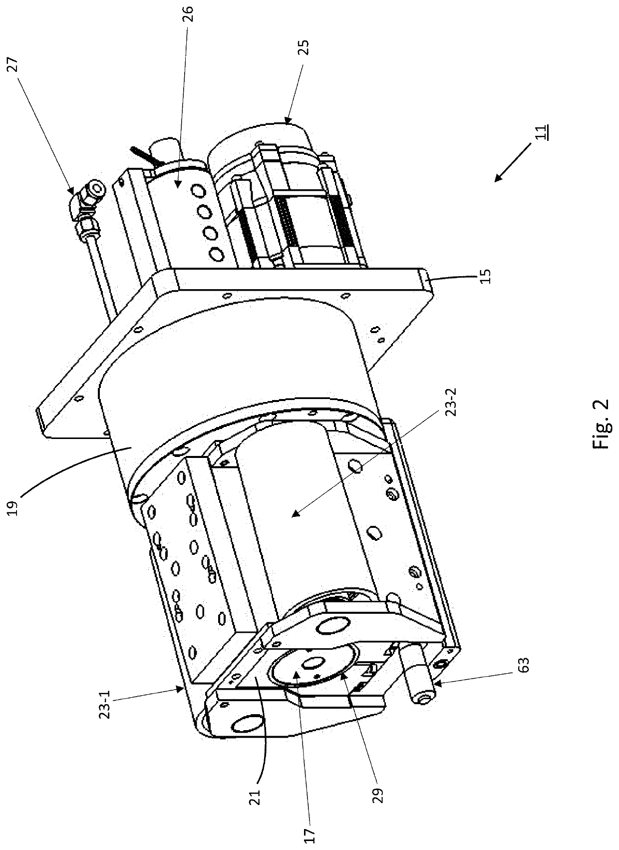
[0032]Referring now to...


PUM

PropertyMeasurementUnit
wrap angleaaaaaaaaaa
gap widthaaaaaaaaaa
conical surfacesaaaaaaaaaa

Abstract

An atomic layer deposition system for depositing thin layers of material onto a common substrate includes a deposition head shaped to define a conical interior cavity into which a conical deposition drum is disposed. Together, the deposition head and the deposition drum define a narrow gap adapted to receive the common substrate, the spacing of the narrow gap being adjustable through acute axial displacement of the deposition head relative to the deposition drum. A pair of rollers advances the substrate through the gap in a first direction, as the deposition head rotates in the opposite direction at a precise rate. Each of the deposition head and deposition drum includes a plurality of separate fluid channels which enable gasses utilized in the deposition process to be delivered into and exhausted from the narrow gap, with the delivery of inert gas on both sides of the substrate effectively creating an air bearing.

Description

CROSS-REFERENCE TO RELATED APPLICATIONS[0001]The present application claims the benefit under 35 U.S.C. 119(e) to U.S. Provisional Patent Application No. 62 / 940,505, which was filed on Nov. 26, 2019 in the names of Daniel Beane et al., the disclosure of which is incorporated herein by reference.FIELD OF THE INVENTION[0002]The present invention relates generally to thin film deposition techniques and, more particularly, to the deposition of thin films through atomic layer deposition.BACKGROUND OF THE INVENTION[0003]Atomic layer deposition (ALD) is a well-known technique for constructing thin films on a deposition substrate. Because atomic layer deposition allows for the construction of highly precise, atomic-level layers on a substrate, ALD is commonly utilized in the fabrication of thin-film semiconductor devices.[0004]Atomic layer deposition is a chemical process, typically performed within a reaction chamber, which involves sequentially exposing a surface with alternate gaseous sp...

Claims


Application Information

Patent Timeline
Patent Type & Authority Applications(United States)
IPC IPC(8): C23C16/54C23C16/455C23C16/458
CPCC23C16/545C23C16/4557C23C16/458C23C16/45544C23C16/45578C23C16/45574C23C16/45551C23C16/4586C23C16/45521
Inventor BEANE, DANIELBERG, JOHN S.BENCHEV, DIMITUR
Owner CARPE DIEM TECH
Why Eureka
Try Eureka