Method and system for controlling a motor vehicle parking brake during a stop

a technology for parking brakes and motor vehicles, applied in brake action initiations, brake systems, mechanical devices, etc., can solve the problems of unfavorable unimpeded drive away operation and insufficient release of parking brakes

Active Publication Date: 2009-12-10
LUCAS AUTOMOTIVE GMBH
View PDF20 Cites 10 Cited by
  • Summary
  • Abstract
  • Description
  • Claims
  • Application Information

AI Technical Summary

Benefits of technology

[0005]It is a feature of the invention is to provide a method and a system for controlling a vehicle equipped with a parking brake that allow a comfortable drive away operation.
[0007]The first value is lower than the second value (wherein both the first and the second value may be selected dynamically in dependence upon a road gradient). The time it takes to release the parking brake may therefore be reduced compared to a parking brake applied to the second value (e.g. a maximum value), thereby enabling a more comfortable and faster driveaway operation. As the parking brake is not always acted upon by the maximum application force, the load profile of the parking brake is moreover optimized. As a result of this optimization, the load of the parking brake drops and less wear occurs at the parking brake. This leads to a lengthening of the maintenance intervals and to an increase of the useful life of the parking brake.
[0018]It is further possible to provide a driver warning device that alerts the driver to a control intervention. The driver warning device may bring the intervention to the attention of the driver optically, acoustically and / or haptically.

Problems solved by technology

In the case of automatic release of the parking brake (for example as a reaction to a requested drive away operation), there is however the problem that, because of the delay that occurs between detection of the drive away operation and full release of the parking brake, the parking brake cannot be fully released quickly enough, with the result that an unimpeded drive away operation is often not possible.

Method used


Image

  • Method and system for controlling a motor vehicle parking brake during a stop
  • Method and system for controlling a motor vehicle parking brake during a stop
  • Method and system for controlling a motor vehicle parking brake during a stop

Examples


first embodiment

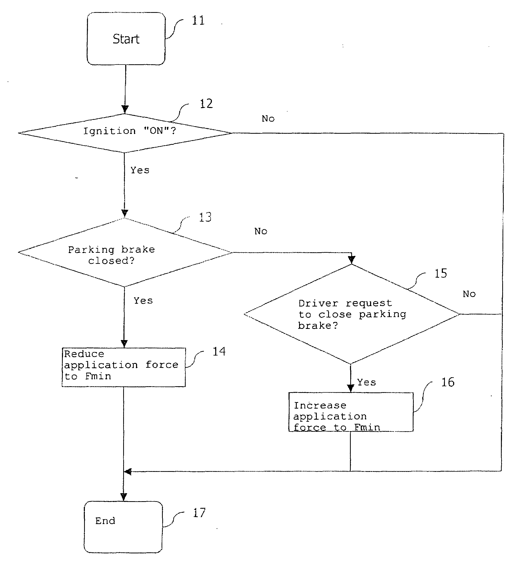
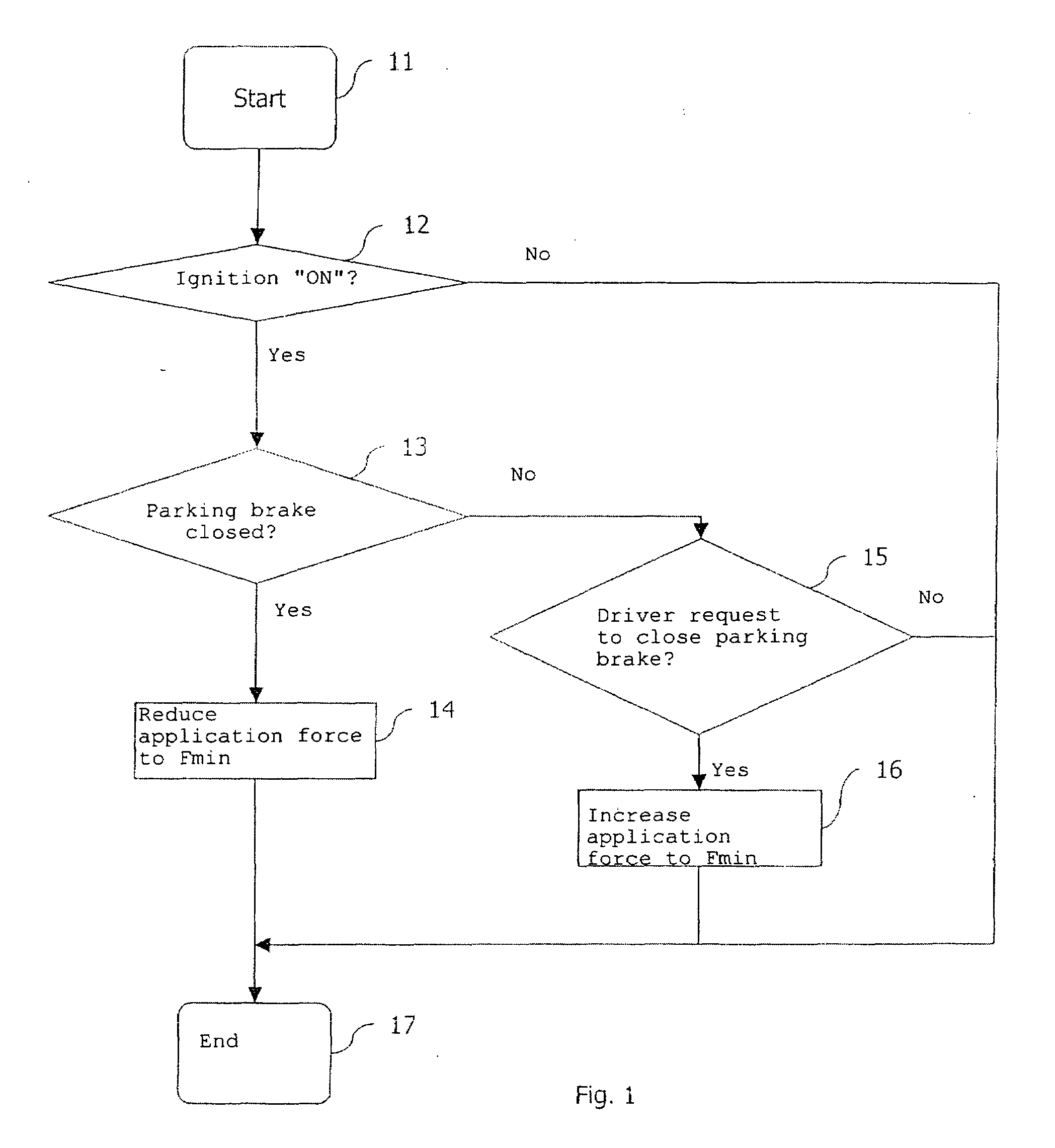
[0023]The flowchart represented in FIG. 1 diagrammatically illustrates the steps of a method of controlling an electric parking brake according to a

[0024]In a first method step 12 the existence of an ignition signal is detected by means of a suitable sensor such as for example an ignition signal sensor or the like. In a second method step 13 it is checked whether the parking brake is closed (for example whether the parking brake is applied by its maximum value or within a specific maximum value range). This may be established at the actuators of the parking brake by means of a force sensor or a displacement sensor or by means of an engine current increase gradient, spindle displacement determination, the current consumption or the like.

[0025]If it is established in step 13 that the parking brake is closed, in the next method step 14 the application force of the parking brake is reduced to a (possibly inclination-dependent) minimum value and held at this value. This means that the ac...

second embodiment

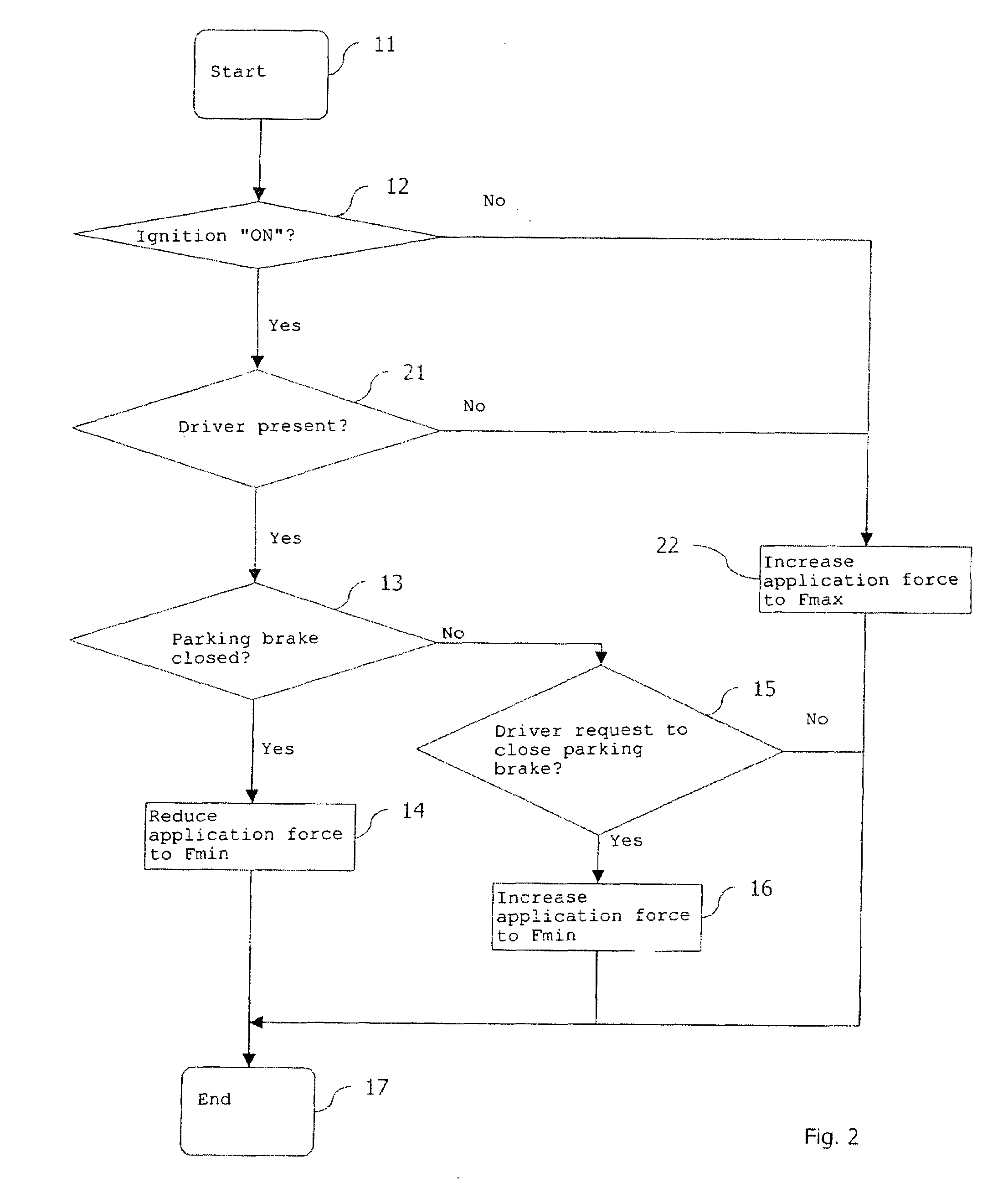
[0028]The second embodiment differs from the embodiment represented in FIG. 1 in that after step 12 in the method step 21 the presence of the driver is detected. The detection of the driver's presence may be detected by means of an interior camera, by means of seat occupation sensors in the driver seat or the like. If the driver is present in the vehicle, the method continues with step 13. If the driver is not in the vehicle but the ignition is switched on, in a method step 22 the application force of the parking brake is increased to a maximum value and held at this value. In other words, the actuators of the parking brake are closed far enough for the application force of the parking brake to ensure that the vehicle reliably remains in its current position even for extended stationary periods. In this case, the maximum value may also be set or re-adjusted in dependence upon the vehicle inclination.

[0029]In step 21 in an alternative manner an open luggage boot, an open bonnet and / o...


PUM


Abstract

A method and a system for controlling a parking brake of a motor vehicle are described. According to the described method, an ignition signal and an actuation state of the parking brake are detected. An application force of the parking brake is then set to a first value in dependence upon the actuation state of the parking brake if the ignition signal is present. If the parking brake was previously in an applied actuation state, the application force is reduced from a second value to the first value. If the parking brake was previously in a released actuation state, the application force is increased to the first value. The first value is sufficient to hold the motor vehicle in its current position.

Description

CROSS-REFERENCE TO RELATED APPLICATIONS[0001]This application is a national stage of International Application No. PCT / EP2006 / 005081 filed May 26, 2006, the disclosures of which are incorporated herein by reference in entirety, and which claimed priority to German Patent Application No. 10 2005 024 834.9 filed May 31, 2005, the disclosures of which are incorporated herein by reference in entirety.BACKGROUND OF THE INVENTION[0002]The invention relates to a method and a system for controlling a parking brake of a motor vehicle during a stop.[0003]For increased comfort in motor vehicles it is known for the parking brake (also known as the emergency brake) to be electrically actuated. The parking brake is for example automatically activated, i.e. applied, as soon as the vehicle is in the stationary state and automatically deactivated, i.e. released, as soon as a drive away (or starting) operation of the vehicle is requested or detected. In the case of automatic activation of the parking...

Claims


Application Information

Patent Timeline
Patent Type & Authority Applications(United States)
IPC IPC(8): B60T13/74
CPCB60T7/107Y10T477/813B60T13/746
Inventor STRAUB, THOMASGILLES, LEOLEITER, RALF
Owner LUCAS AUTOMOTIVE GMBH
Why Eureka
Try Eureka