
Shift control device for vehicles

一种换档控制、车辆的技术,应用在传动装置控制、带有齿的元件、皮带/链条/齿轮等方向,能够解决时间长等问题,达到降低初始切换位置不同的可能性的效果

Active Publication Date: 2012-09-12
TOYOTA JIDOSHA KK
View PDF5 Cites 4 Cited by
  • Summary
  • Abstract
  • Description
  • Claims
  • Application Information

AI Technical Summary

Problems solved by technology

Therefore, when the switching position information stored in the nonvolatile storage device is unknown, compared with the case where the switching position information is a P position or a non-P position, it is necessary to determine the switching position based on the vehicle speed through the vehicle control device. information, the shift control device receives more processes such as it, so it takes longer time to complete the P wall position detection control or the non-P wall position detection control from the time of the travel enabling operation.

Method used


Image

  • Shift control device for vehicles
  • Shift control device for vehicles
  • Shift control device for vehicles

Examples


Embodiment

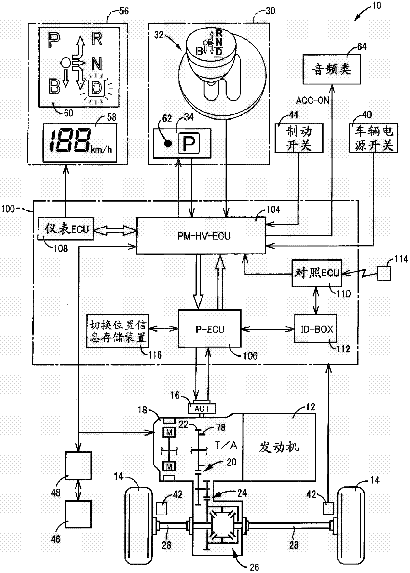
[0034] figure 1 It is a diagram illustrating a schematic configuration of a power transmission path from the engine 12 constituting the vehicle 10 to which the present invention is applied to the drive wheels 14, and is a diagram illustrating the main components of a control system provided in the vehicle 10 to control the parking lock device 16 and the like. Partial frame diagram. figure 1 Among them, the vehicle 10, including the parking lock device 16, the transmission 18, the shift operation device 30, etc., adopts the shift-by-wire operation for electrically switching the gear position related to the driving of the vehicle 10, that is, the gear position (gear range) of the transmission 18. (SBW) way. Furthermore, the transmission 18 is preferably used in, for example, a FF (Front Front Drive) type vehicle mounted transversely in the vehicle 10, and transfers the power of the engine 12, which is an internal combustion engine as a driving force source for travel, from the ...


PUM


Abstract

Provided is a shift control device for vehicles for minimizing the prolongation of the required time from the time when the driver performs an operation to enable the vehicle to travel to the time when the vehicle comes to a travel possible state. A switch position update permission means (136) permits update of the switch position information stored in a switch position information storage device (116) on condition that a wall position detection control means (132) performs switch position recognition control. When a P-ECU (shift control device) (106) is switched from a nonactuated state to an actuated state, a switch position update means (134) updates the switch position information stored in the switch position information storage device (116) after the switch position update means (134) is permitted to update the switch position information by the switch position update permission means (136). Therefore, since the occasions the switch position information stored in the switch position information storage device (116) is updated assuming the switch position information is indefinite decrease, the prolongation of the required time can be minimized when the operation to enable the travel is performed after the P-ECU (106) is turned on next time.

Description

technical field [0001] The present invention relates to a vehicle including a parking lock device for selectively switching a switching position into a locked position and an unlocked position for restricting rotation of wheels by driving of an actuator, in particular based on the The shift-by-wire technology for shifting vehicle gears electronically with the required signal for switching positions. Background technique [0002] There is known a shift control device for a vehicle including a parking lock for switching a rotary gear rotating together with a wheel to a locked state in which a lock gear meshes with the rotary gear and an unlocked state in which the locked state is released. The device operates the actuator including the parking lock device based on the request signal, and switches between the locked state and the unlocked state, thereby electrically switching gears related to vehicle running, so-called shift-by-wire (SBW) )Way. For example, if the operating p...

Claims


Application Information

Patent Timeline
Patent Type & Authority Applications(China)
IPC IPC(8): F16H61/28F16H63/34
CPCF16H63/3466F16H63/483F16H59/10
Inventor 北折一郎堤贵彦金井理上野弘记关谷圭介铃木俊成
Owner TOYOTA JIDOSHA KK
Learn More