Precision full-floating drum brake

A drum brake and full-floating technology, which is applied in the direction of mechanically driven drum brakes and brake parts, can solve problems such as uneven friction surfaces, improve driving safety, achieve better braking effects, and prolong service life. Effect

Inactive Publication Date: 2010-11-24
杨群英
View PDF1 Cites 4 Cited by
  • Summary
  • Abstract
  • Description
  • Claims
  • Application Information

AI Technical Summary

Problems solved by technology

[0005] The above structure enables the left and right brake shoes to achieve floating braking with the brake drum during braking, and increases the friction plate and the friction plate of the brake drum to make the brakin

Method used


Image

  • Precision full-floating drum brake
  • Precision full-floating drum brake
  • Precision full-floating drum brake

Examples


Embodiment Construction

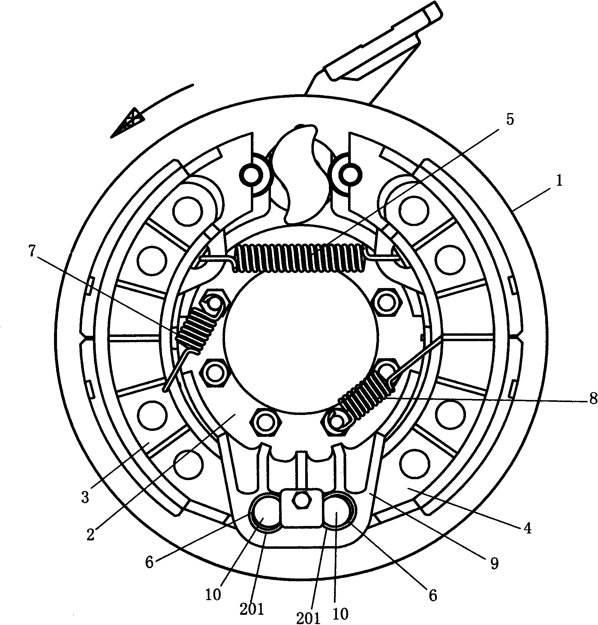
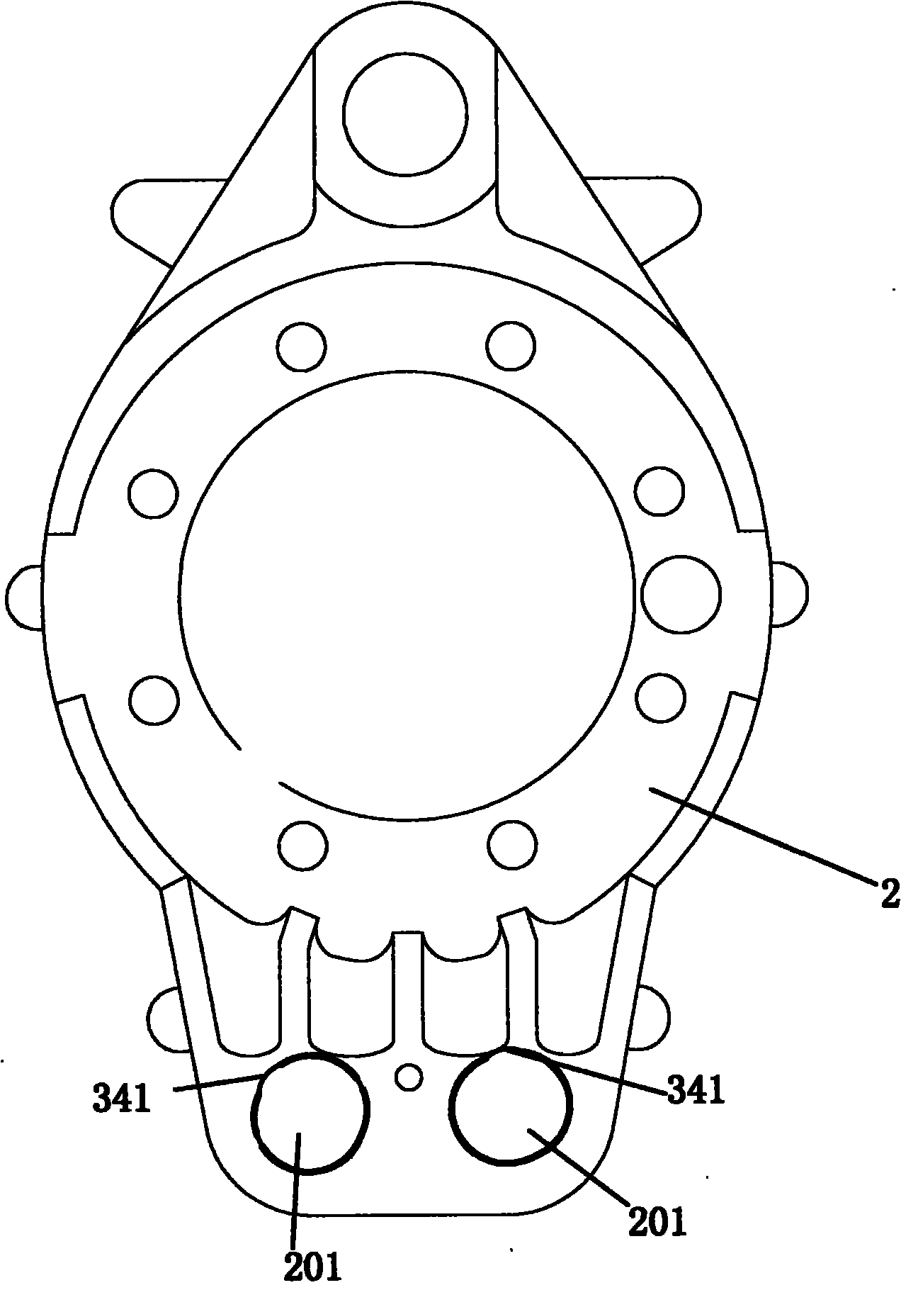
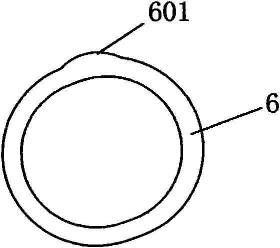
[0032] Such as Figures 1 to 4 Shown: a precision full-floating drum brake, including a brake drum 1, a brake base plate 2, master and slave brake shoes 3 and 4 symmetrically arranged on the brake base plate 2, master and slave brake shoes 3 The supporting end connection holes 301, 401 of , 4 are axially connected with the clamping part 9 at one end corresponding to the brake base plate 2, the open ends of the main and slave brake shoes 3, 4 are free ends, and one camshaft passes through the brake base plate 2 and the other The through hole of the convex part at one end is in contact with the rollers at the free ends of the master and slave brake shoes 3 and 4, and one end of the rollers located at the master and slave brake shoes 3 and 4 is provided with a return spring 5, and the clamping part 9 of the above-mentioned brake base plate 2 It is arranged as upper and lower splints, with a gap left in the middle. A pair of positioning holes 201 are opened on the corresponding po...


PUM


Abstract

The invention discloses a precision full-floating drum brake and aims to improve the relation between a brake baseplate and a brake shoe. An improved clamp connection part of the brake baseplate consists of an upper layer splint and a lower layer splint between which a gap is formed, wherein corresponding positions of the upper layer splint and the lower layer splint of the clamp connection part are provided with a pair of elliptical positioning holes with certain gaps between upper and lower ends; taking the circle center of the brake soleplate as a reference central point, the positioning hole on a left side deflects inwards and forms an included angle of between 16 and 45 degrees with the central point; and the positioning hole on a right side deflects outwards and forms an included angle of between 46 and 83 degrees with the central point. The invention provides the drum brake with precise floating quantity. The brake has the advantages of making friction between a friction plate and the brake drum uniform, prolonging the service life of the friction plate and the brake, ensuring more reliable braking, high braking efficiency, and more comfortable driving, and enhancing driving safety.

Description

technical field [0001] The invention relates to a brake used for automobiles, in particular to a precision full-floating drum brake. Background technique [0002] The traditional drum brake is mainly composed of brake base plate, brake drum, brake shoe, wheel cylinder or camshaft, return spring, positioning pin and other components. The brake bottom plate is installed on the fixed position of the axle, such as: the front and rear axle housings, which are fixed, and are equipped with brake shoes, camshafts or wheel cylinders and other expansion devices, return springs, and support pins to withstand braking. rotation torque. Each brake drum has a pair of brake shoes, and friction discs are inlaid on the brake shoes. The brake drum is installed on the hub wheel rotation shaft (the output half shaft of the bridge), and is a part that rotates with the wheel. It is made of a certain amount of cast iron and is shaped like a drum. When braking, the wheel cylinder piston or the ca...

Claims


Application Information

Patent Timeline
IPC IPC(8): F16D51/22F16D65/09
Inventor 杨群英
Owner 杨群英
Why Eureka
Try Eureka