
Magnetic sensor

Inactive Publication Date: 2009-12-17
TDK CORPARATION
View PDF18 Cites 5 Cited by
  • Summary
  • Abstract
  • Description
  • Claims
  • Application Information

AI Technical Summary

Benefits of technology

[0007]The lateral spin-valve device is advantageous over the vertical spin-valve device in that the height in the laminating direction can be made lower because of its structure. In the conventional lateral spin-valve device, however, an electrically insulating layer for electrically insulating a nonmagnetic conductive layer where spins accumulate and a lower magnetic shield layer disposed under the nonmagnetic conductive layer from each other is provided between the nonmagnetic conductive layer and lower magnetic shield layer. This increases the height in the laminating direction by the thickness of the electrically insulating layer, thereby inhibiting the magnetic sensor from improving its resolution.
[0008]In view of circumstances mentioned above, it is an object of the present invention to provide a magnetic sensor which can improve the resolution.

Problems solved by technology

This increases the height in the laminating direction by the thickness of the electrically insulating layer, thereby inhibiting the magnetic sensor from improving its resolution.

Method used


Image

  • Magnetic sensor
  • Magnetic sensor
  • Magnetic sensor

Examples


first embodiment

[0039]A thin-film magnetic recording and reproducing head 100A will now be explained as an example of the magnetic sensor in accordance with the first embodiment.

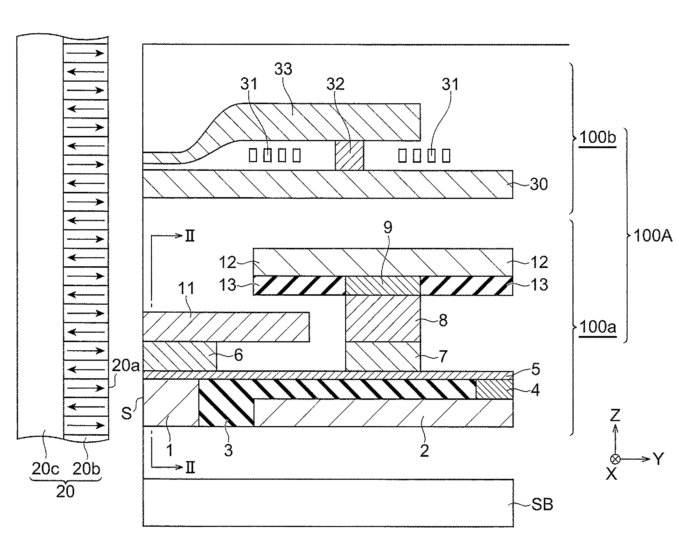
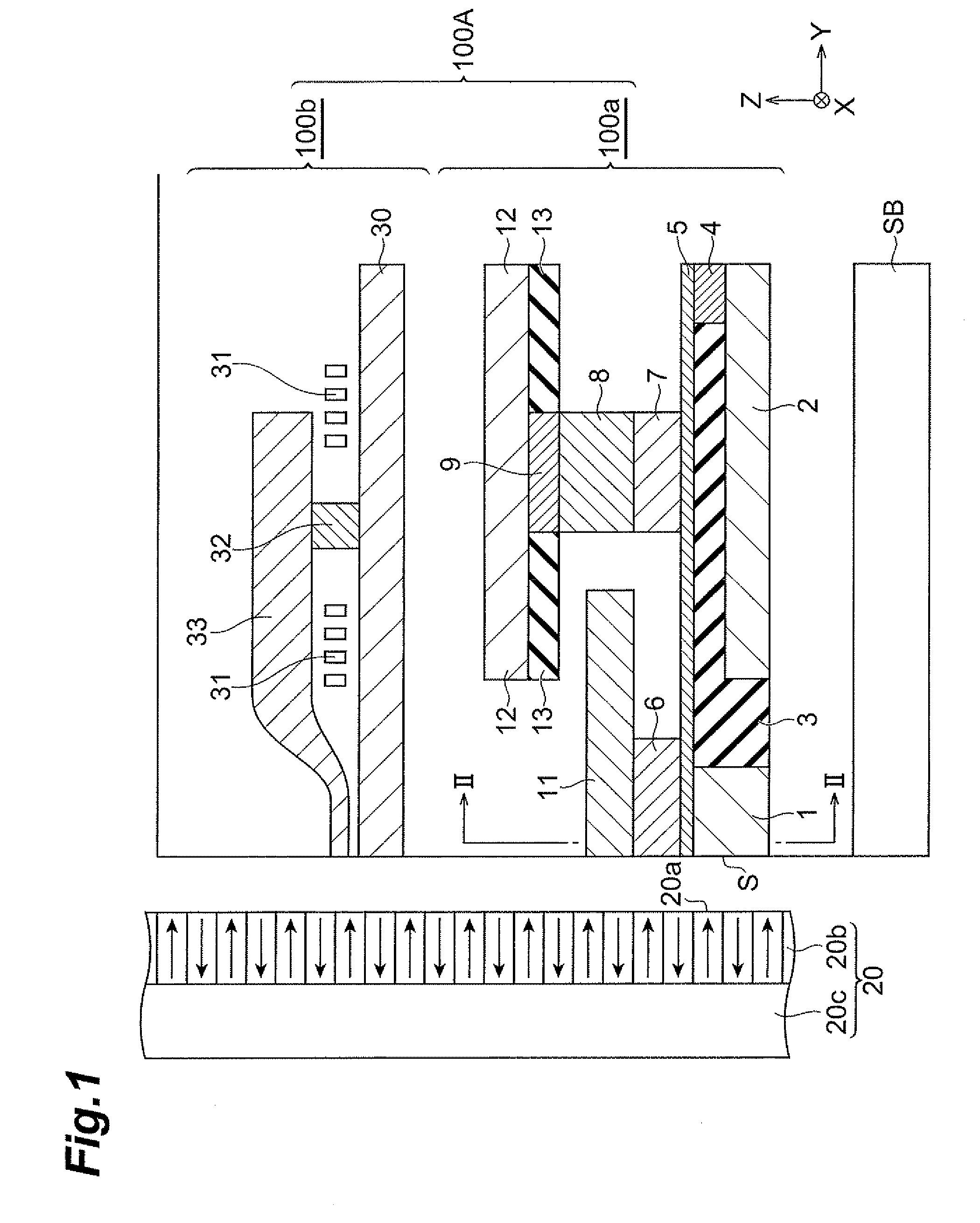
[0040]FIG. 1 is a partial sectional view illustrating the thin-film magnetic recording and reproducing head 100A.

[0041]The thin-film magnetic recording and reproducing head 100A carries out operations for recording and reading magnetic information at such a potion that its air bearing surface (ABS) S opposes a recording surface 20a of a magnetic recording medium 20.

[0042]The magnetic recording medium 20, which includes a recording layer 20b having the recording surface 20a and a soft magnetic backing layer 20c laminated on the recording layer 20b, advances in the direction of Z in the drawing relative to the thin-film magnetic recording and reproducing head 100A.

[0043]The thin-film magnetic recording and reproducing head 100A comprises a magnetic sensor 100a for reading records from the magnetic recording medium 20 and a ma...

second embodiment

[0080]A thin-film magnetic recording and reproducing head 100B as an example of the magnetic sensor in accordance with the second embodiment will now be explained.

[0081]FIG. 4 is a partial sectional view illustrating the thin-film magnetic recording and reproducing head 100B.

[0082]The thin-film magnetic recording and reproducing head 100B illustrated in FIG. 4 differs from the thin-film magnetic recording and reproducing head 100A in accordance with the first embodiment in terms of the lower first magnetic shield layer 1, lower second magnetic shield layer 2, and first electrically insulating layer 3, which will be explained alone.

[0083]In this embodiment, the lower first magnetic shield layer 1 and lower second magnetic shield layer 2 are formed integrally with each other and electrically connected to each other. The lower first magnetic shield layer 1 opposing the free magnetization layer 6 projects toward the nonmagnetic conductive layer 5 so as to be positioned closer to the non...

third embodiment

[0085]A thin-film magnetic recording and reproducing head 100C as an example of the magnetic sensor in accordance with the third embodiment will now be explained.

[0086]FIG. 5 is a partial sectional view illustrating the thin-film magnetic recording and reproducing head 100C.

[0087]The thin-film magnetic recording and reproducing head 100C illustrated in FIG. 5 differs from the thin-film magnetic recording and reproducing head 100A in accordance with the first embodiment in terms of the lower first magnetic shield layer 1, lower second magnetic shield layer 2, first electrically insulating layer 3, and first electrode 4, which will be explained alone.

[0088]In this embodiment, the lower first magnetic shield layer 1 and lower second magnetic shield layer 2 are formed integrally with each other and electrically connected to each other. The lower first magnetic shield layer 1 opposing the free magnetization layer 6 projects toward the nonmagnetic conductive layer 5 so as to be positioned...


PUM


Abstract

A magnetic sensor comprises a nonmagnetic conductive layer, a free magnetization layer disposed on a first part of the nonmagnetic conductive layer, a fixed magnetization layer disposed on a second part of the nonmagnetic conductive layer different from the first part, upper and lower first magnetic shield layers opposing each other through the nonmagnetic conductive layer and free magnetization layer interposed therebetween, upper and lower second magnetic shield layers opposing each other through the nonmagnetic conductive layer and fixed magnetization layer interposed therebetween, and an electrically insulating layer disposed between the lower second magnetic shield layer and the nonmagnetic conductive layer, while the lower first magnetic shield layer is arranged closer to the nonmagnetic conductive layer than is the lower second magnetic shield layer.

Description

BACKGROUND OF THE INVENTION[0001]1. Field of the Invention[0002]The present invention relates to a magnetic sensor.[0003]2. Related Background Art[0004]As magnetic sensors used in thin-film magnetic recording and reproducing heads and the like, magnetoresistive (MR) devices utilizing giant magnetoresistive effect (GMR), tunnel magnetoresistive effect (TMR), and the like have conventionally been known.[0005]In general, a GoM device has a multilayer structure in which a free magnetization layer, a nonmagnetic conductive layer, a fixed magnetization layer, and an upper electrode are sequentially formed on a lower electrode. A typical TMR device has a multilayer structure in which a free magnetization layer, a nonmagnetic insulating barrier layer, a fixed magnetization layer, and an upper electrode are sequentially formed on a lower electrode. Such a magnetoresistive device in which a free magnetization layer and a fixed magnetization layer are laminated in a vertical direction will her...

Claims


Application Information

Patent Timeline
IPC IPC(8): G11B5/33G11B5/127
CPCG11B5/398G01R33/098
Inventor SASAKI, TOMOYUKI
Owner TDK CORPARATION
Features
  • Generate Ideas
  • Intellectual Property
  • Life Sciences
  • Materials
  • Tech Scout
  • Unparalleled Data Quality
  • Higher Quality Content
  • 60% Fewer Hallucinations
Learn More