Magnetic field measuring element, magnetic field measuring device, and magnetic field measuring system

Active Publication Date: 2021-06-17
JAPAN OIL GAS & METALS NAT +2
View PDF0 Cites 0 Cited by
  • Summary
  • Abstract
  • Description
  • Claims
  • Application Information

AI Technical Summary

Benefits of technology

[0051]The invention makes it possible to lo

Problems solved by technology

Meanwhile, in the case of a high temperature superconducting SQUID that uses a YBa2Cu3Ox oxide conductor as a superconductor and can be operated in liquid nitrogen, inter-superconductor junction technology has yet to be developed.
Th

Method used


Image

  • Magnetic field measuring element, magnetic field measuring device, and magnetic field measuring system
  • Magnetic field measuring element, magnetic field measuring device, and magnetic field measuring system
  • Magnetic field measuring element, magnetic field measuring device, and magnetic field measuring system

Examples


Example

First Embodiment

(Configuration of Magnetic Field Measuring Element E)

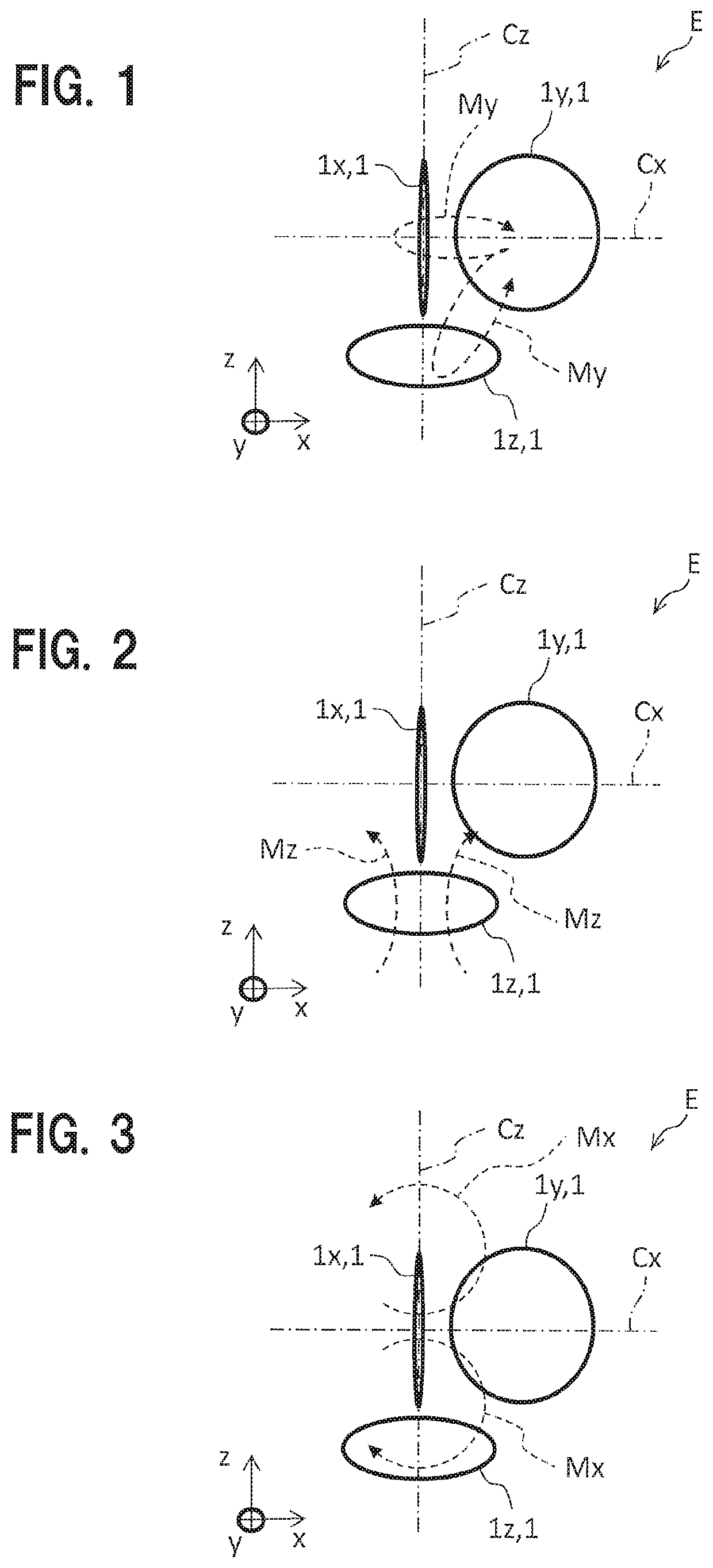
[0089]FIGS. 1 to 3 are diagrams each illustrating an example of arrangement of coils in a magnetic field measuring element E according to a first embodiment. Note that in FIGS. 1 to 4, SQUID magnetic sensors 1x to 1z represent detection coils 3 and the other components are omitted so as to make it easy to understand the pictures. In addition, each SQUID magnetic sensor 1 has substantially the same structure as of FIG. 31.

[0090]The SQUID magnetic sensor 1z (1), which is the first SQUID magnetic sensor, is disposed on a plane (first plane) perpendicular to the z axis. Specifically, the SQUID magnetic sensor 1z is horizontally placed with respect to the ground. The SQUID magnetic sensor 1x (1), which is the second SQUID magnetic sensor, is disposed on the central axis Cz that extends, from the center of the SQUID magnetic sensor 1z, vertically with respect to the detection plane of the SQUID magnetic sensor 1z.

[0091]...

Example

Second Embodiment

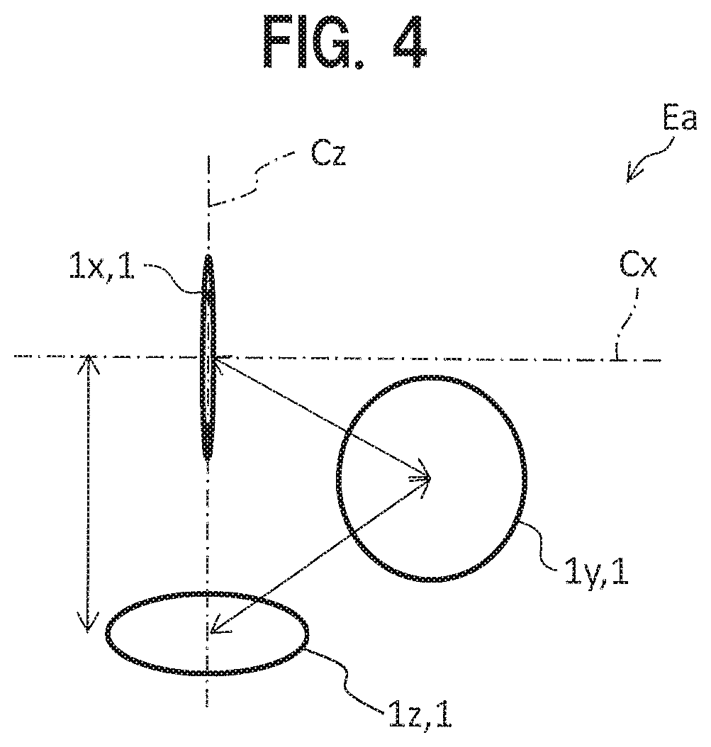
[0111]FIG. 4 is a diagram illustrating positional relation between SQUID magnetic sensors 1 in a magnetic field measuring element Ea according to a second embodiment.

[0112]In the magnetic field measuring element E shown in FIGS. 1 to 3, the SQUID magnetic sensors 1x and 1y are disposed at the same height relative to the SQUID magnetic sensor 1z. Specifically, the center of the SQUID magnetic sensor 1y is disposed on the central axis Cx. As such, the height of the whole magnetic field measuring element E shown in FIGS. 1 to 3 is made lower. That is, in the magnetic field measuring element E shown in FIGS. 1 to 3, the SQUID magnetic sensors 1x to 1z are arranged so as to equal the distance from the bottom surface of the magnetic field measuring element E (the coil surface of the SQUID magnetic sensor 1z) to the upper end of each of the SQUID magnetic sensors 1x and 1y. However, the arrangement is acceptable as long as the respective SQUID magnetic sensors 1 are in par...

Example

Third Embodiment

(Magnetic Field Measuring System Z)

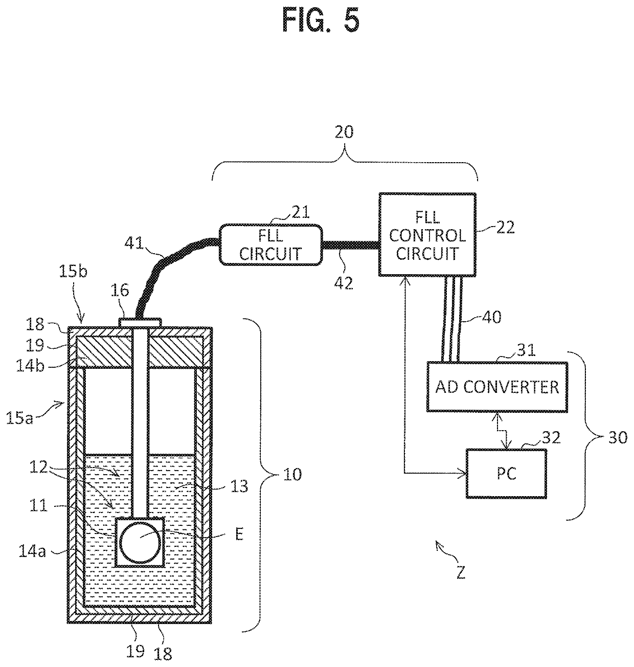
[0116]FIG. 5 illustrates function blocks as a configuration example of a magnetic field measuring system Z according to an embodiment of the invention.

[0117]The magnetic field measuring system Z includes a magnetic field measuring unit (magnetic field measuring device) 10, which is a cryostat, a control circuit unit 20, and a data processing unit 30. Note that in FIG. 5, the magnetic field measuring unit 10 is represented by a schematic cross-sectional view.

[0118]The magnetic field measuring unit 10 includes a magnetic field measuring element E having, as components, a plurality of SQUID magnetic sensors 1 for measuring a magnetic flux.

[0119]In addition, the control circuit unit 20 is to control the magnetic field measuring unit 10 and has an FLL circuit 21 and an FLL control circuit 22. The FLL circuit 21 and the FLL control circuit 22 will be described below.

[0120]Further, the data processing unit 30 is to record magnetic signals,...


PUM


Abstract

A magnetic field measuring element includes a Superconducting QUantum Interference Device magnetic sensors, the first sensor disposed either on a second plane perpendicular to a first plane including a coil surface of the third sensor and which includes the center of the third sensor, or in the vicinity of the second plane, and a second sensor disposed either on a third plane perpendicular to the first plane and the second plane, or in the vicinity of the third plane. The center of the first sensor is present either on a straight line which passes through the center of the third sensor and is perpendicular to the first plane, or in the vicinity of said straight line, and the center of the second sensor is present in a position displaced from a line joining the center of the third sensor and the center of the first sensor.

Description

TECHNICAL FIELD[0001]The present invention relates to technology for a magnetic field measuring element, a magnetic field measuring device, and a magnetic field measuring system using a plurality of SQUID magnetic sensors.BACKGROUND ART[0002]SQUID (Superconducting QUantum Interference Device) magnetic sensors are magnetic sensors using superconductivity. Thus, the SQUID magnetic sensors are used while cooled to a superconducting critical temperature or lower by using a liquid refrigerant such as liquid helium or liquid nitrogen or by using, for instance, a freezer.[0003]FIG. 31 is a schematic diagram of a common SQUID magnetic sensor 1.[0004]The SQUID magnetic sensor 1 is a magnetic flux-voltage conversion element, the output voltage of which can be changed by a superconducting loop-interlinked magnetic flux.[0005]Each SQUID magnetic sensor 1 is structured by including either one or two Josephson junction portions 2 on a closed loop (superconducting loop) called a SQUID inductor 8.[...

Claims


Application Information

Patent Timeline
IPC IPC(8): G01R33/035G01R33/02H01L39/22
CPCG01R33/0356H01L39/223G01R33/0206H10N60/10H10N60/12
Inventor TSUKAMOTO, AKIRAHATO, TSUNEHIROTANABE, KEIICHIMOTOORI, MASAYUKIISHIKAWA, HIDEHIRO
Owner JAPAN OIL GAS & METALS NAT
Why Eureka
Try Eureka