Loop connector and closed-circuit forming connector

Active Publication Date: 2012-03-22
MOLEX INC
View PDF15 Cites 1 Cited by
  • Summary
  • Abstract
  • Description
  • Claims
  • Application Information

AI Technical Summary

Benefits of technology

[0015]In accordance with the Present Disclosure, the loop connector and the closed-circuit forming connector have a configuration in which the loop terminal which is integrally formed and includes a pair of terminals and the connecting portion is press-fitted into the housing. Due to such a configuration, it is made possible to enable the positioning of the terminal to be appropriately held and mutua

Problems solved by technology

However, the conventional loop connector has a large format and a complex structure because it is used for connecting the conductive traces of the first circuit board 891 and the conductive traces of the second circuit board 892, and it is thus practically impossible to be used for connecting two conductive traces of a sheet of circuit board.
In such a case, it is practically impossible to use the conventional loop connector for con

Method used


Image

  • Loop connector and closed-circuit forming connector
  • Loop connector and closed-circuit forming connector
  • Loop connector and closed-circuit forming connector

Examples


Embodiment Construction

[0030]While the Present Disclosure may be susceptible in different forms, there is shown in the Figures, and will be described herein in detail, with the understanding that the disclosure is to be considered an exemplification of the principles of the Present Disclosure, and is not intended to limit the Present Disclosure to that as illustrated.

[0031]In the Present Disclosure, directional representations—i.e., up, down, left, right, front, rear and the like, used for explaining the structure and movement of the various elements of the Present Disclosure, are relative. These representations are appropriate when the elements are in the position shown in the Figures. If the description of the position of the elements changes, however, it is assumed that these representations are to be changed accordingly.

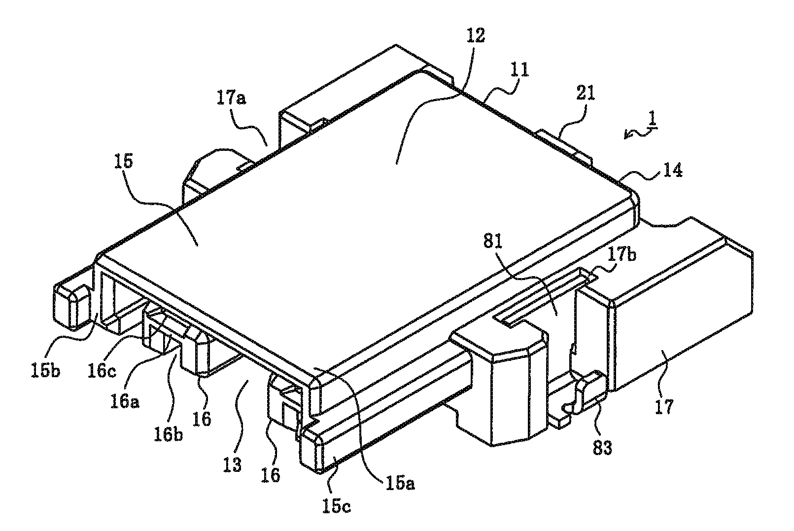
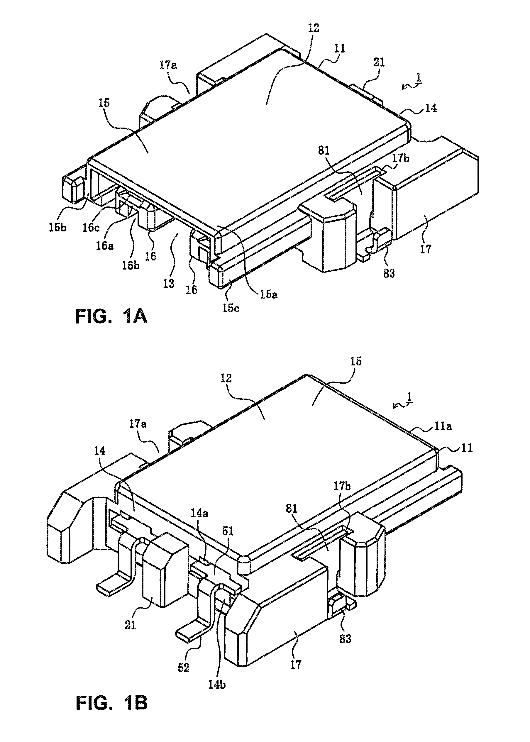
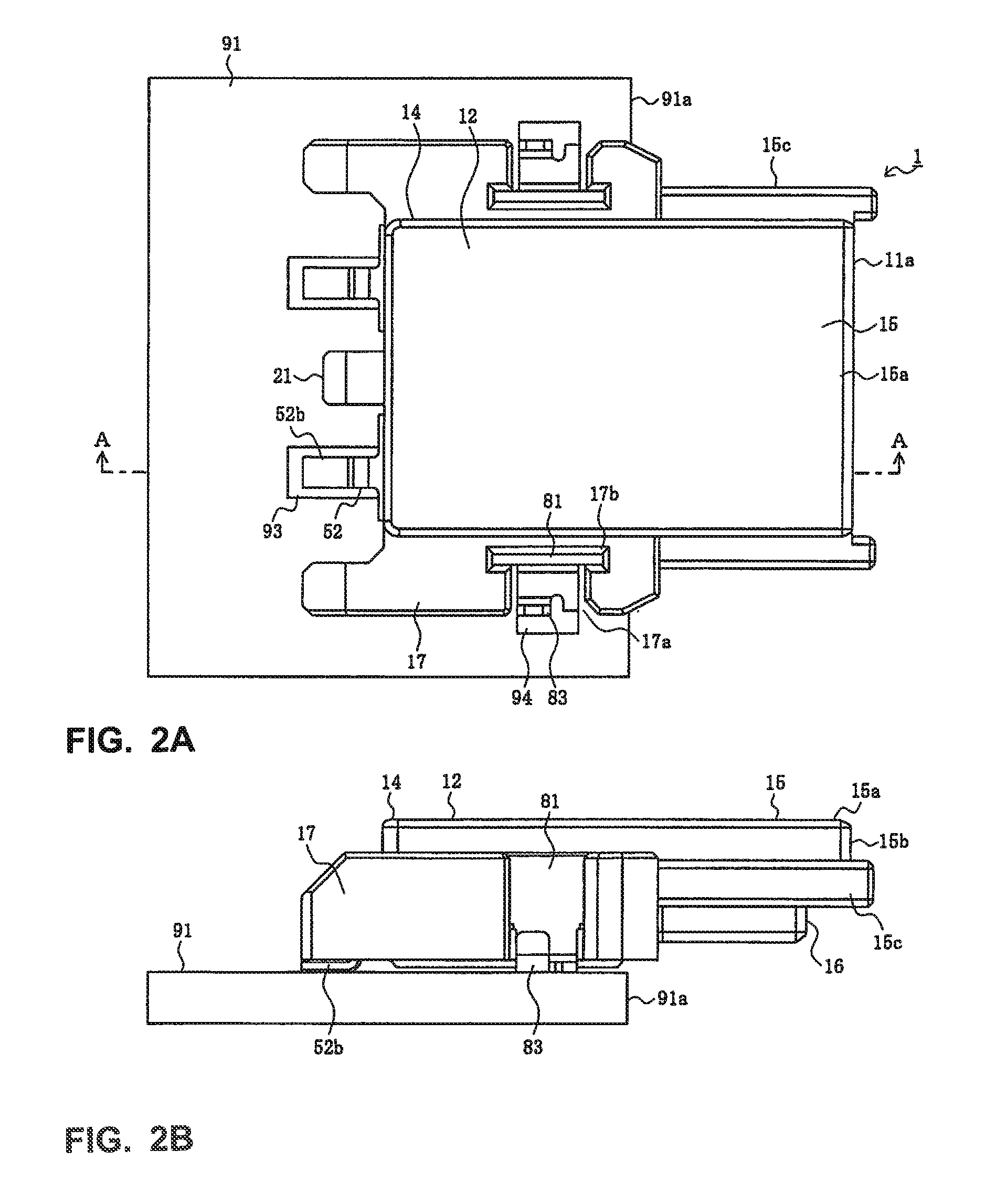
[0032]The loop connector includes the first connector 1 and the second connector 101, and is configured to electrically connect a pair of conductive traces of the board 91, thereby for...


PUM


Abstract

A loop connector comprises first and second connectors. The first connector has a first housing and a pair of first terminals, is configured to be surface-mounted on a top surface of a board, and has a fitting face thereof extending in a direction intersecting the top surface of the board. The second connector has a second housing and a second terminal configured to contact one of the first terminals, is configured to engage the first connector, and has a fitting face thereof extending in a direction intersecting an extending direction of the second terminal. The second housing is provided with a second terminal accommodation-concave portion. The second terminal is provided with a pair of terminal bodies and a connecting portion to connect thereto, the terminal bodies being perpendicular to the connecting portion when the second terminal is press-fit into the second terminal accommodation-concave portion.

Description

[0001]REFERENCE To RELATED APPLICATIONS[0002]The Present Disclosure claims priority to prior-filed Japanese Patent Application No. 2009-122039, entitled “Loop Connector And Closed-Circuit Forming Connector,” and filed 20 May 2009, the contents of which is fully incorporated in its entirety herein.BACKGROUND OF THE PRESENT DISCLOSURE[0003]The Present Disclosure relates to a loop connector and a closed-circuit forming connector.[0004]Loop connectors have been used for electrically connecting a pair of circuit boards, such as that disclosed in Japanese Utility Model Application No. 54-93795. Such a loop connector has a pair of circuit boards which are arranged in parallel.[0005]FIG. 13 illustrates another conventional loop connector. Referring to FIG. 13, the housing of a loop connector 811 is engaged, by fitting, with one end of a first circuit board 891 which is one from a pair of edge cards and with one end of a second circuit board 892 which is the other one from the pair of edge c...

Claims


Application Information

Patent Timeline
IPC IPC(8): H01R13/28H01R12/00H01R12/57H01R12/71H01R12/78H01R12/79H01R31/08
CPCH01R12/727H01R31/08
Inventor KOBAYASHI, KOTARO
Owner MOLEX INC
Why Eureka
Try Eureka