Energy-storing type automobile in-situ turning machine

A U-turn machine and energy storage technology, which is applied in vehicle maintenance, shunting equipment, vehicle control devices, etc., can solve the problems of limited expansion space and high cost, and achieve the effect of alleviating parking difficulties

Inactive Publication Date: 2019-01-04
应国珍
View PDF9 Cites 0 Cited by
  • Summary
  • Abstract
  • Description
  • Claims
  • Application Information

AI Technical Summary

Problems solved by technology

[0004] The streets and alleys of the city and the old residential areas are generally located in the central urban area, and the expansion space is very limited. It is expensive to solve the problem by demolition. For this reason, we still need to develop facilities that can alleviate the problem, and wait for the future system of the city. Retrofit to solve the problem completely

Method used


Image

  • Energy-storing type automobile in-situ turning machine
  • Energy-storing type automobile in-situ turning machine
  • Energy-storing type automobile in-situ turning machine

Examples


Embodiment Construction

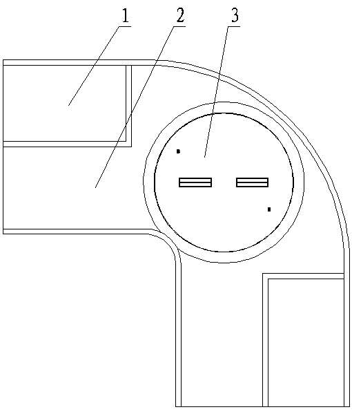
[0023] As shown in the figure, the vehicle turn-around machine 3 is located at the turning of the ground road 2, and is generally arranged on the inner side of the turning of the ground road 2.

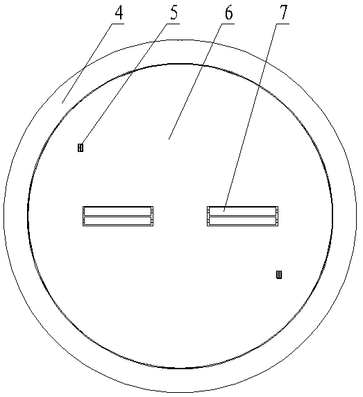
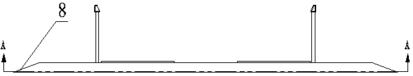
[0024] The edge of the chassis 4 of the automobile in-situ U-turn machine 3 is provided with a slope 8, which is convenient for the vehicle to enter and exit; rotate.

[0025] Controller 5 is located at the left front end, the right rear end of turntable assembly 6 respectively, and is used for the vehicle that two-way enters, and people just needn't get off to make arrangements for.

[0026] A positioner 9 is set on the back of the turntable of the turntable assembly 6, and the positioner 9 will stop the brake when the turntable assembly 6 rotates to the set angle according to the setting of the controller 5.

[0027] The energy storage drum 7 in the accumulator 13 is located at both sides in the middle of the turntable assembly 6 , the energy storage drum 7 is connected with the en...


PUM


Abstract

The invention provides an energy-storing type automobile in-situ turning machine, which is arranged at a turning point of a ground road, does not consume electricity and is not restricted by an area,and can help the automobile to turn in-situ depending on the power of the automobile. The energy-storing type automobile in-situ turning machine is characterized in that: the automobile in-situ turning machine is arranged at the turning point of the ground road. The automobile in-situ turning machine comprises a chassis with ramp at the edge, a rotary table assembly arranged in the chassis, and controllers respectively arranged at the left front end and the right rear end of the rotary table assembly for use by vehicles entering in both directions. The energy storage drum is arranged on both sides in the middle of the rotary table assembly. The turntable assembly is provided with a positioner on the back side and is distributed with pulley devices. Each pulley device comprises a powered pulley device and a non-power pulley device. The non-power pulley device is arranged in the support of the rotary table. The front end of the pulley device is provided with a front pulley, the rear endof the pulley device is provided with a rear pulley, and the front end of the front pulley is provided with a rounded corner for end face positioning. The powered pulley device is arranged in the bracket of the rotary table, the front end of the power pulley device is provided with a front pulley, the rear end of the power pulley device is provided with a rear pulley, the front end of the front pulley is provided with a rounded corner for positioning the end surface, and the power pulley device is driven by an energy accumulator through a connecting shaft.

Description

technical field [0001] The invention relates to an in-situ U-turn machine for automobiles. Background technique [0002] With the rapid development of our country's economy, people's income has risen sharply, and it has become a reality for cars to enter ordinary people's homes, which directly leads to the generation and further aggravation of urban parking problems, and it is urgent to solve the urban parking problem. [0003] Now most of the major cities in the country adopt the way of occupying the road for parking, and some cities still have the phenomenon of parking on the main arterial road, which seriously affects the normal road traffic and further reduces the road capacity and driving speed. In addition, in the streets and alleys of the city and in the old residential quarters, there are many narrow and winding roads, and there is a serious lack of suitable parking spaces. However, the phenomenon of illegal parking and encroaching on the roads by nearby residents' m...

Claims


Application Information

Patent Timeline
Patent Type & Authority Applications(China)
IPC IPC(8): B60S13/02
CPCB60S13/02
Inventor 应国珍
Owner 应国珍
Why Eureka
Try Eureka