

Derrick arrangement of tools for replacing steel arch bridge suspender and replacing method thereof
A technology for steel arch bridges and suspenders, applied in bridges, bridge maintenance, bridge reinforcement, etc., can solve problems such as difficult to ensure structural safety, bridge deck deformation, difficult drilling of solid arch rings, and suspenders less than 20 years old. Arch ring structure and appearance, easy to control synchronization, simple structure effect
- Summary
- Abstract
- Description
- Claims
- Application Information
AI Technical Summary
Problems solved by technology
Method used
Image

Examples
Embodiment Construction
[0047] The present invention will be further described in detail below in conjunction with the accompanying drawings and specific embodiments.
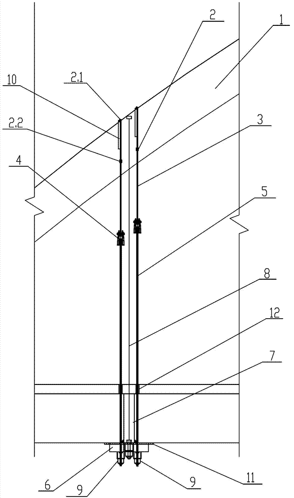
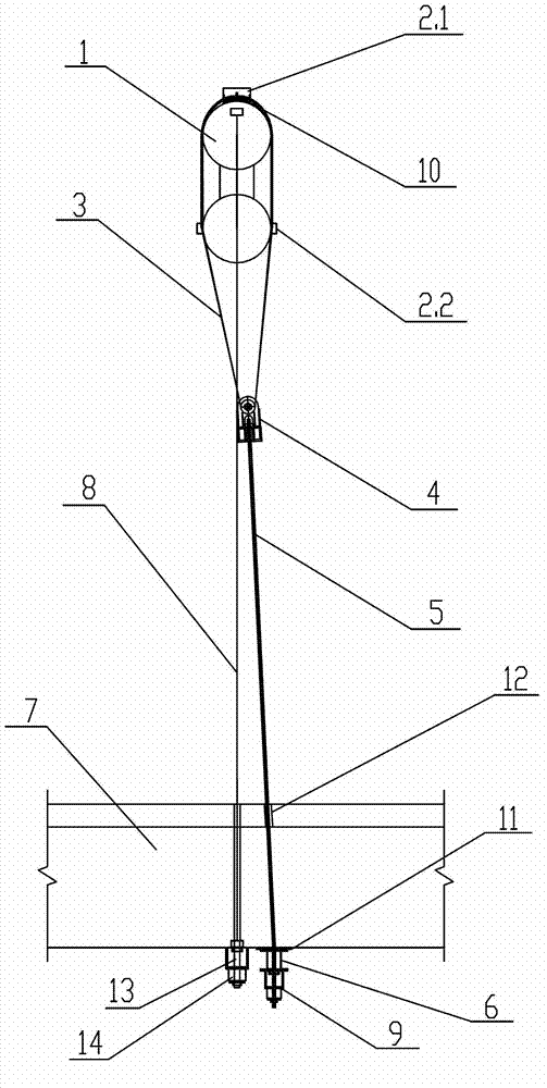
[0048] figure 1 , 2 The tool suspender device for replacing the suspender of the steel arch bridge shown, it includes a limit device 2 symmetrically arranged on both sides of the suspender 8, a steel wire rope 3, an intermediate conversion device 4 and a steel strand 5, and fixed on the suspender beam 7 Hanging device 6 below. A 5mm thick rubber backing plate 11 is arranged between the hanging device 6 and the boom beam 7 .
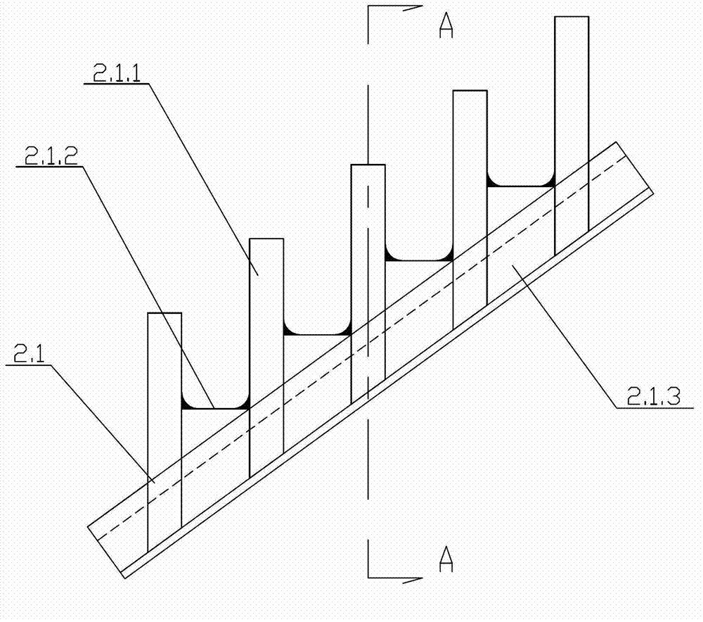
[0049] The limiting device 2 includes a horizontal limiting device 2.1 installed on the top arc of the arch ring 1 and a vertical limiting device 2.2 installed on both sides of the arch ring 1 . The vertical and horizontal projection distance between the horizontal limit devices 2.1 arranged on both sides of the boom 8 is greater than the width of the boom beam 7, the vertical limit devices 2.2 on both sides o...
PUM
 Abstract
Description
Claims
Application Information