Mouse wheel device

Inactive Publication Date: 2014-08-21
CHENG UEI PRECISION IND CO LTD
View PDF6 Cites 1 Cited by
  • Summary
  • Abstract
  • Description
  • Claims
  • Application Information

AI Technical Summary

Benefits of technology

[0009]As described above, the mouse wheel device of the present invention utilizes at least two scroll wheels and the track sheathed on the outer side surfaces of the scroll wheels with the scroll wheels being apart arranged side-by-side, instead of one large scr

Problems solved by technology

As a result, the touch area of the exposed part of the scroll wheel 11

Method used


Image

  • Mouse wheel device
  • Mouse wheel device
  • Mouse wheel device

Examples


Example

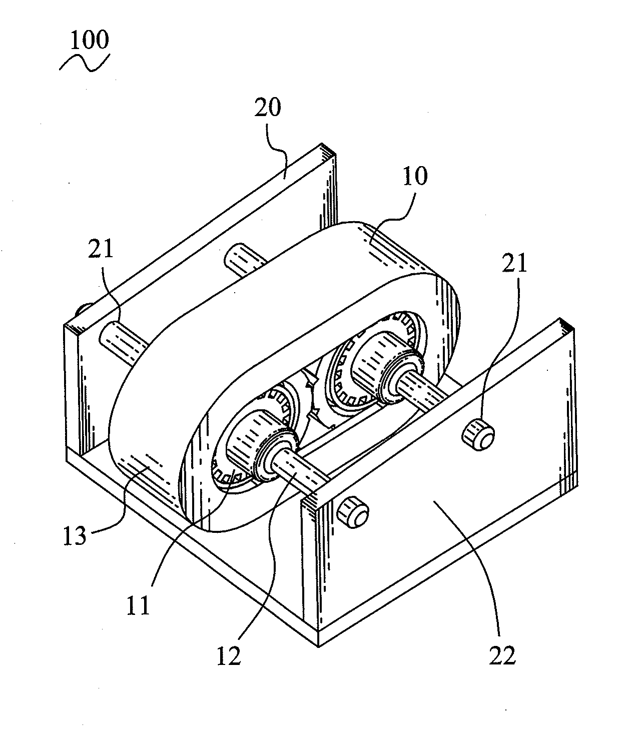
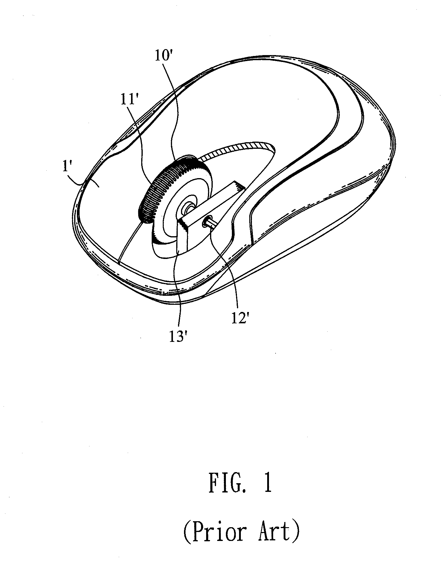
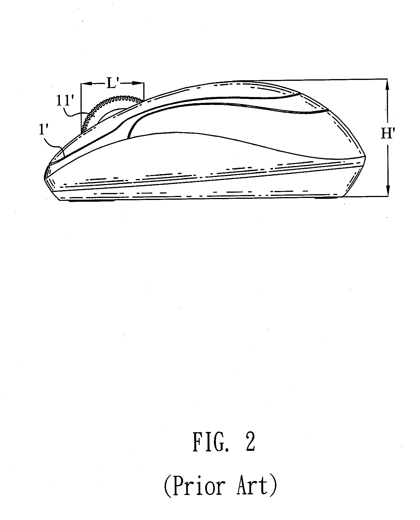
[0018]Referring to FIG. 4 and FIG. 7, a mouse wheel device 100 according to an embodiment of the present invention is assembled in a mouse 200 with a thinner thickness H. The mouse wheel device 100 includes a mouse wheel assembly 10 and a mounting bracket 20, wherein the mouse wheel assembly 10 is pivoted to the mounting bracket 20.

[0019]Referring to FIGS. 4-7, the mouse wheel assembly 10 includes at least two scroll wheels 11, at least two wheel shafts 12 and a track 13. Each of the scroll wheels 11 has a through hole 111 axially penetrating through a center thereof. The outer side surface of the scroll wheel 11 defines a plurality of meshing grooves 112 arranged at regular intervals along the periphery thereof. Each of the scroll wheels 11 is axially mounted to the middle of one of the wheel shafts 12 via the through hole 111.

[0020]The track 13 is sheathed on the outer side surfaces of the scroll wheels 11 with the scroll wheels 11 being apart arranged side-by-side. The inner surf...


PUM


Abstract

A mouse wheel device includes a mouse wheel assembly including at least two scroll wheels, at least two wheel shafts and a track, and a mounting bracket. Each scroll wheel has a through hole axially penetrating through a center thereof. The outer side surface of the scroll wheel defines a plurality of meshing grooves. Each of the scroll wheels is axially mounted to the middle of one of the wheel shafts via the through hole. The track is sheathed on the outer side surfaces of the scroll wheels with the scroll wheels being apart arranged side-by-side. The inner surface of the track protrudes inward to form a plurality of meshing ribs engaged with the meshing grooves to drive the scroll wheels and the wheel shafts to rotate in the same direction. The mouse wheel assembly is pivoted to the mounting bracket through two ends of each wheel shaft.

Description

BACKGROUND OF THE INVENTION[0001]1. Field of the Invention[0002]The present invention relates to a mouse technology field, and more particularly to a mouse wheel device assembled in a mouse.[0003]2. The Related Art[0004]Referring to FIG. 1, a conventional mouse wheel device 10′ is shown. The mouse wheel device 10′ is assembled in a mouse 1′ and includes a scroll wheel 11′, a wheel shaft 12′ and a mounting bracket 13′. The scroll wheel 11′ is rotatably mounted to the mounting bracket 13′ by the wheel shaft 12′. In use, some functions of a computer can be controlled by the mouse 1′ via scrolling the scroll wheel 11′.[0005]Referring to FIG. 2, in order to make the mouse 1′ easy to use for users, the scroll wheel 11′ of the mouse 1′ is designed with a larger size so as to have a longer length L′ of the exposed part, so that can provide a larger touch area for the convenience of the users using the mouse 1′. But it relatively causes the mouse 1′ have a thicker thickness H′.[0006]With the...

Claims


Application Information

Patent Timeline
IPC IPC(8): G06F3/0354
CPCG06F3/03543
Inventor LEE, TSUNG SHIHTING, YU HSIANG
Owner CHENG UEI PRECISION IND CO LTD
Why Eureka
Try Eureka