
Pressure transmission system comprising a device for identifying membrane ruptures and connection adapter comprising a device for identifying membrane ruptures

Inactive Publication Date: 2007-04-03
EHNDRESS KHAUZER GMBKH KO KG
View PDF5 Cites 1 Cited by
  • Summary
  • Abstract
  • Description
  • Claims
  • Application Information

AI Technical Summary

Benefits of technology

[0013]The arrangement of the sensor for monitoring a material property of the transfer medium in the pressure chamber opening or in another section communicating with the pressure chamber by way of the pressure chamber opening has, additionally, the advantage that it leads also to a transport of the contaminants by convection, or flow, of the transfer medium.
[0014]This should frequently cause a faster detectability of the contaminants than the purely diffusive transport in the arrangement of Bastiaan. Assuming, for example, a pressure chamber working volume of 100 mm3 and an opening diameter of 1 mm, then this means during an overload pressure pulse a displacement of the total working volume in the opening by about 127 mm. In this way, the contaminants can reach the sensor with the transfer medium considerably faster than is the case with the arrangement of Bastiaan.
[0015]Equally, temperature fluctuations can lead to a convective transport of the contaminants. A temperature change in the pressure conducting line of, for example, 10° C. leads, in the case of a volume expansion coefficient of about 10−3 / K, a pressure conducting line length of 10 m and an internal diameter of 1 mm, to a volume change of about 80 mm3, which corresponds to a movement of the liquid column of about 100 mm at the end of the pressure conducting line. The described convective transport to the sensor is more effective, the longer the length of the pressure conducting line in comparison to the separation of the sensor from the dividing membrane.

Problems solved by technology

A very high manufacturing cost is required to equip this multiplicity of sensors with the conductivity probe proposed by Bastiaan.
Such a constraint is unacceptable for many applications.
Moreover, transport of the contaminants to the sensor happens purely diffusively in the described pressure transmitter.
This can lead to a large time delay between the occurrence of a leak and the detection of the contamination resulting therefrom, depending on the depth of the dead-end hole and the particulars of the installation of the pressure transmitter.

Method used


Image

  • Pressure transmission system comprising a device for identifying membrane ruptures and connection adapter comprising a device for identifying membrane ruptures
  • Pressure transmission system comprising a device for identifying membrane ruptures and connection adapter comprising a device for identifying membrane ruptures
  • Pressure transmission system comprising a device for identifying membrane ruptures and connection adapter comprising a device for identifying membrane ruptures

Examples


Embodiment Construction

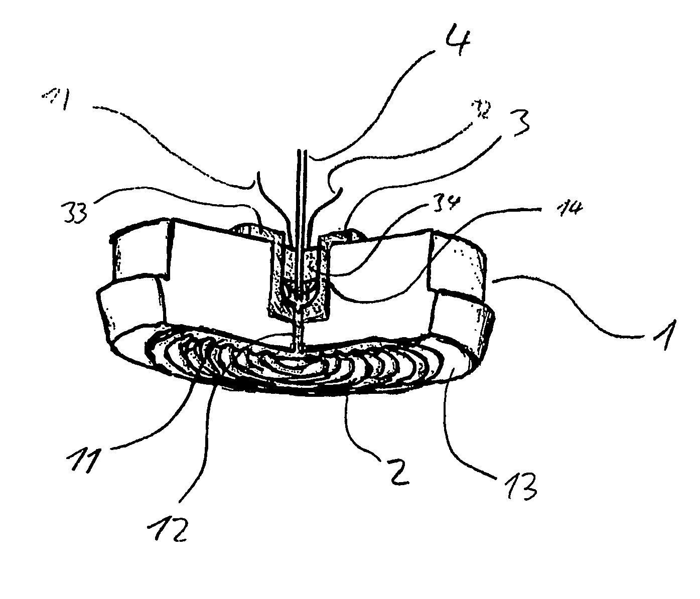
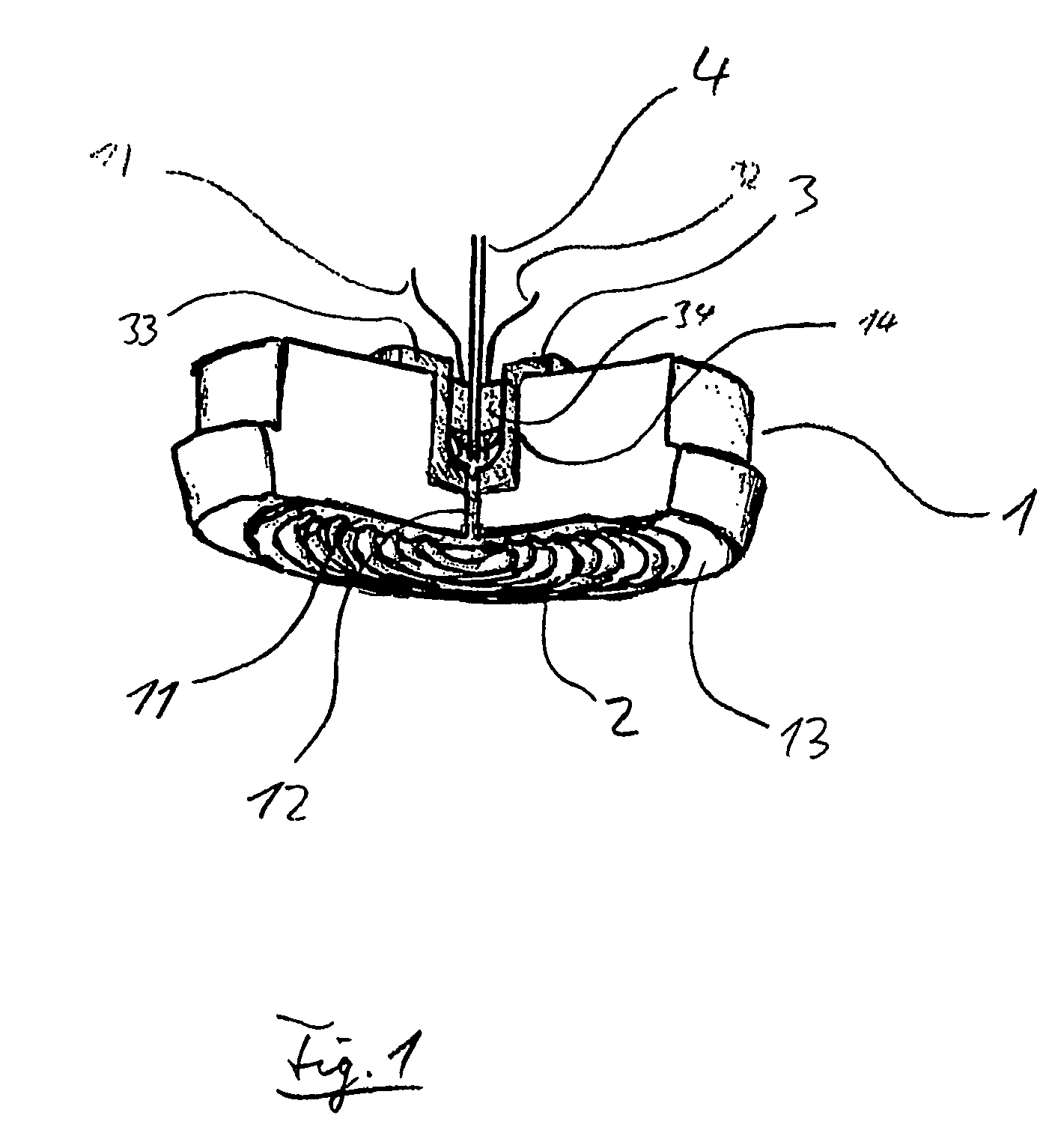
[0020]The pressure transmitter shown in FIG. 1 includes a platform 1, which has a preferably essentially cylindrically symmetric construction. Dividing membrane 2 is secured at its edge 21 onto the front side 13 of the platform, so that a pressure chamber 11 is formed between the dividing membrane 2 and the platform. The front side 13 of the platform 1 can be provided in usual manner with a membrane bed, against which the dividing membrane 2 is pressed in the case of overload.

[0021]The pressure chamber 11 has an opening 12 for transmission of the pressure prevailing in the pressure chamber. The opening 12 is preferably constructed as a capillary line. Opening 12 extends in the preferred embodiment to a pressure line connection 14, which preferably is in the form of an essentially cylindrical, or axially symmetric, recess on the side of the platform 1 opposite to that containing dividing membrane 2.

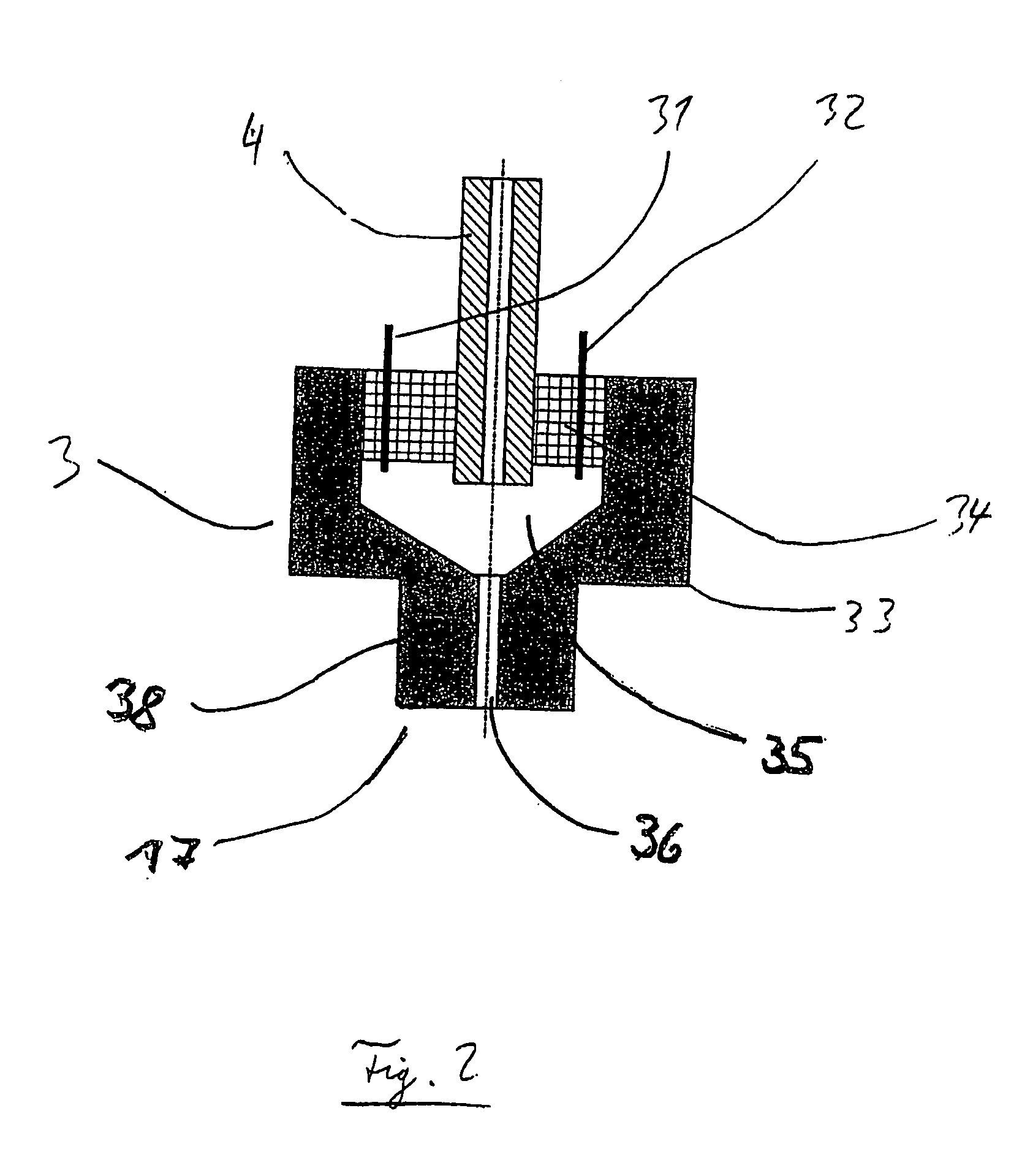
[0022]The connection of the pressure conducing line 4 occurs, in a preferred embodimen...


PUM


Abstract

A pressure transmitter for transferring a pressure from a pressure prevailing in a first medium onto a second medium includes a pressure chamber between a platform and a dividing membrane, wherein the pressure chamber is fillable with the second medium and has a pressure chamber opening, through which the pressure can be transmitted by means of the second medium to a pressure measurement cell. The pressure transmitter includes a sensor for monitoring a material property of the second medium, preferably a conductivity sensor with at least one electrode, which sensor can detect contaminants in the second medium from the first medium following a rupture of the dividing membrane on the basis of changes in the monitored material property. The sensor is in flow connection with the pressure chamber by way of the pressure chamber opening.

Description

FIELD OF THE INVENTION[0001]The invention relates to a pressure transmitter, or mediator, with diaphragm seal, for transferring a pressure from a pressure prevailing in a first medium onto a second medium, more specifically to pressure transmitters having: a platform; a dividing, or separating, membrane, or diaphragm, which is secured at its edge onto the platform, wherein a first surface of the dividing membrane, facing away from the platform, can be brought into contact with the first medium, and a second surface of the dividing membrane, facing toward the platform, forms with the platform a pressure chamber, which can be filled with the second medium, wherein the pressure chamber has a pressure chamber opening, through which the pressure can be transferred by means of the second medium; and a sensor for monitoring a property of a medium contained in the chamber.BACKGROUND OF THE INVENTION[0002]Devices of this type are, in addition to other uses, used for pressure measurement in a...

Claims


Application Information

Patent Timeline
IPC IPC(8): G01L9/16G01L19/06G01L1/00G01M3/16
CPCG01L19/0672G01M3/16G01L27/007
Inventor WOEST, WOLFGANG
Owner EHNDRESS KHAUZER GMBKH KO KG
Learn More