Apparatus to Monitor Flow Assurance Properties in Conduits

Inactive Publication Date: 2014-10-02
ASTRO TECH GRP LLC
View PDF18 Cites 1 Cited by
  • Summary
  • Abstract
  • Description
  • Claims
  • Application Information

AI Technical Summary

Benefits of technology

[0005]The invention includes a combination of sensors that are strategically placed along the pipeline to measure critical properties such as temperature and pressure of the flow product. The sensors of the subject invention are a combination of fiber optic sensing devices that are specifically designed to measure a range of properties within particular bandwidth, with a method to reduce light attenuation over the long pipeline distances. The pipeline is typically subsea and can range widely in diameter. In many cases the pipeline has a coating that acts as a barrier to the corrosive sea water and additional thermal barriers.
[0006]The invention has the capability of m

Problems solved by technology

As hot gases that flow from the well are subjected to cooling, hydrates can precipitate from the product and results in flow restrictions and in extreme cases can completely block the pipeline.
In other instances slow buildup of paraffin wax on the interior of the pipeline can cause flow re

Method used


Image

  • Apparatus to Monitor Flow Assurance Properties in Conduits
  • Apparatus to Monitor Flow Assurance Properties in Conduits
  • Apparatus to Monitor Flow Assurance Properties in Conduits

Examples


Embodiment Construction

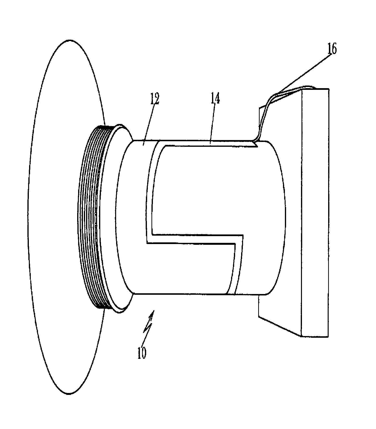
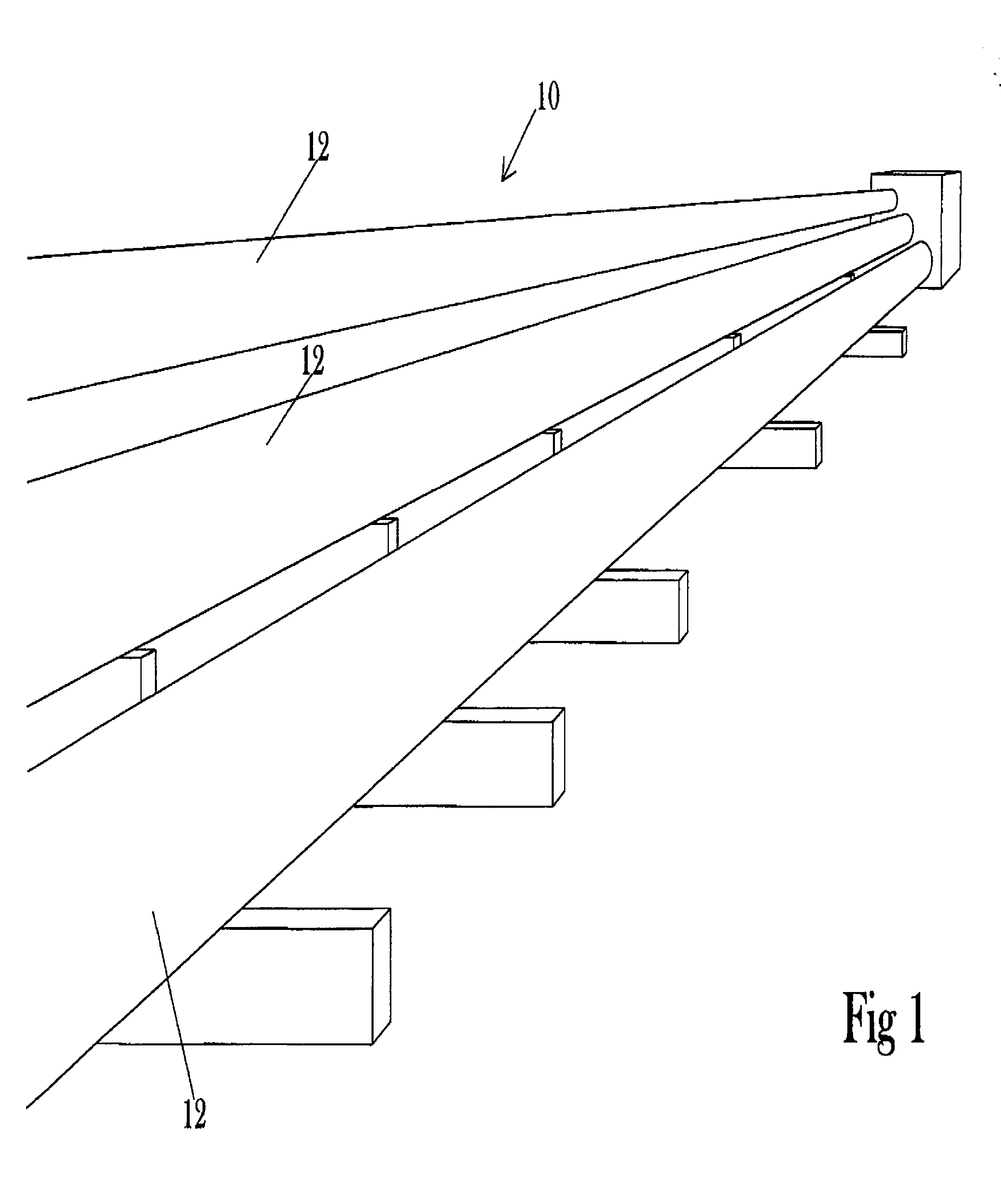
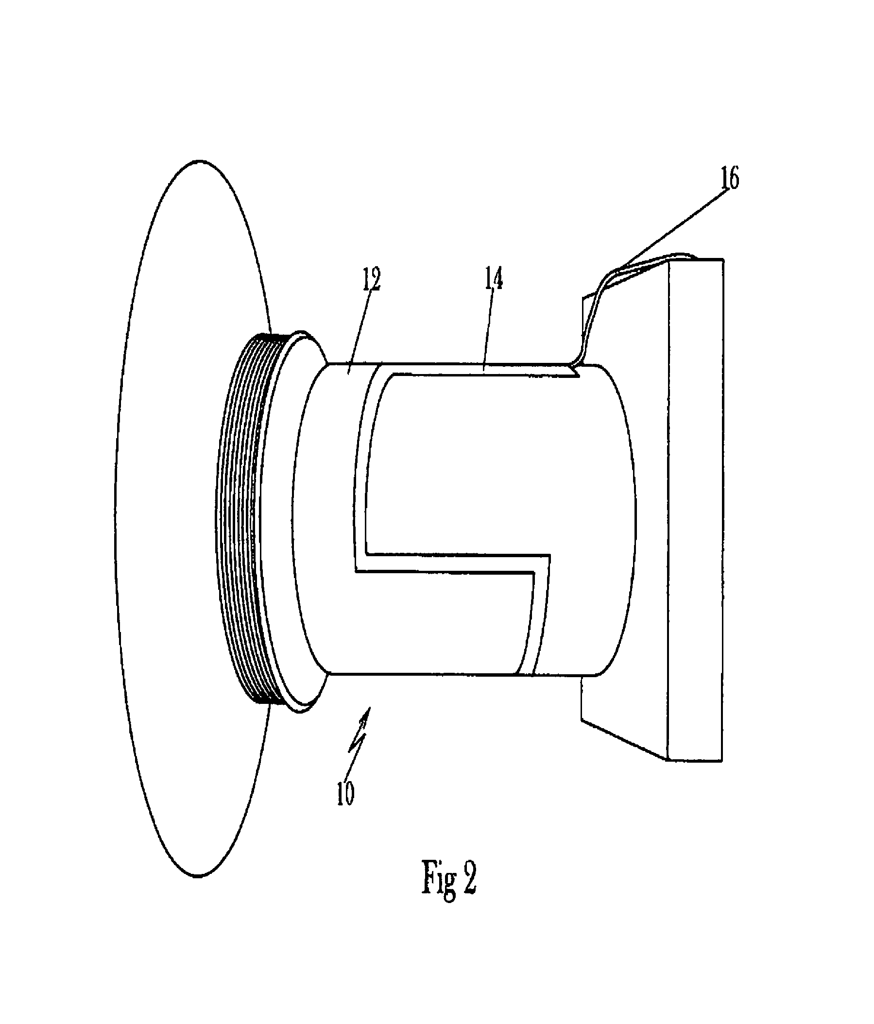
[0013]As shown in FIG. 1, a typical pipeline 10 is positioned for deployment in a subsea environment. In the preferred embodiment of the invention, the fiber optic sensors are attached directly to the outer wall 12 by an epoxy 14, as shown in FIG. 2. The data collected by a sensor array is then conducted to a fiber breakout assembly or collector 18 via the fiber optic cable 16, which is attached to the sensors in the array, see FIG. 3. The collected data is then conducted to a topside control room (not shown) via the conductor 20.

[0014]An alternative collector 22 is shown in FIG. 4, wherein a plurality of sensor array cables 16a-16e may be connected to a single collector 22 for transmitting the collected data to the topside control room via cable 20.

[0015]The cabling, connectors, breakout assemblies and support hardware are designed to provide ruggedness during installation and provide attenuation free light transfer. The system is designed for long service life and has measure inco...


PUM


Abstract

A combination of sensors are strategically placed along a pipeline to measure critical properties such as temperature and pressure of the flow product. The sensors are a combination of fiber optic sensing devices that are specifically designed to measure a range of properties within particular bandwidth, with a method to reduce light attenuation over the long pipeline distances. The pipeline is typically subsea and can range widely in diameter. In many cases the pipeline has a coating that acts as a barrier to the corrosive sea water and additional thermal barriers.

Description

CROSS REFERENCE TO RELATED APPLICATION[0001]This application claims priority based on the Provisional Application No. 61 / 242,746, filed on Sep. 15, 2010, by David V. Brower, entitled: “An Apparatus to Monitor Flow Assurance Properties in Conduits,” which is incorporated by reference herein.BACKGROUND OF THE INVENTIONDiscussion of the Prior Art[0002]The invention is directed to a device and methodology for measuring the flow assurance properties in conduits and pipeline that are used to transport oil and gas products. Pipelines that link wellhead s to a processing site are increasing in length. Many of these pipelines are deployed in subsea environments where water temperatures can cool the pipe that carries the hydrocarbon form the production well. As hot gases that flow from the well are subjected to cooling, hydrates can precipitate from the product and results in flow restrictions and in extreme cases can completely block the pipeline. In other instances slow buildup of paraffin ...

Claims


Application Information

Patent Timeline
IPC IPC(8): G01L11/02
CPCG01L11/025
Inventor BROWER, DAVID V.
Owner ASTRO TECH GRP LLC
Why Eureka
Try Eureka