LED lamp wick module and LED bulb with the same

An LED wick and LED bulb technology, applied in the field of lighting, can solve the problems of reducing the light intensity of LED bulbs, shortening the service life of LED bulbs, etc., and achieve the effects of improving color rendering index and luminous efficiency, prolonging service life, and large heat dissipation area

Inactive Publication Date: 2014-03-26
KUSN KAIWEI ELECTRONICS
View PDF9 Cites 1 Cited by
  • Summary
  • Abstract
  • Description
  • Claims
  • Application Information

AI Technical Summary

Problems solved by technology

The current LED light bulbs, in order to obtain soft white light suitable for lighting, generally directly coat phosphor powder on the surface of the blue LED light. Long-term exposure to the heat of the lamp substrate causes the light decay of the LED bulb, that is, the light intensity of the LED bulb is reduced, and the service life of the LED bulb is reduced

Method used


Image

  • LED lamp wick module and LED bulb with the same
  • LED lamp wick module and LED bulb with the same
  • LED lamp wick module and LED bulb with the same

Examples


Embodiment 1

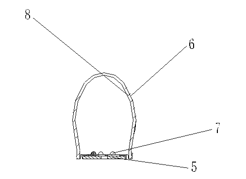
[0019] Such as figure 1 As shown, the part indicated by the label 2 is the LED wick module in this embodiment, which includes a substrate 5 and a wick cover 6 sleeved on the substrate 5. The wick cover 6 is shaped like a cone. There is a blue LED lamp 7, the inner surface of the wick cover 6 is covered with a phosphor layer 8, the wick cover 6 covered with the phosphor layer 8 can expand the light-emitting angle of the LED lamp, and also reduce the light decay of the LED lamp Phenomenon.

[0020] The above phosphor layer 8 is a remote phosphor layer, which can be combined with the blue LED lamp 7 for better fluorescence excitation.

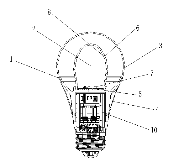
[0021] Such as figure 2 , image 3 As shown, the LED light bulb in this embodiment includes a casing 1, and the casing 1 includes a lampshade 3 and a lamp body 4 that are connected to each other. The connection method between the lampshade 3 and the lamp body 4 can be threaded connection, buckle connection or other methods. The lampshade 3 i...

Embodiment 2

[0026] Others are the same as in Embodiment 1, except that two blue LED lamps are arranged on the substrate 5, the lamp body 4 is made of a ceramic lamp body, and the substrate 5 is made of a ceramic substrate to meet different usage needs.

Embodiment 3

[0028] Others are the same as the content of embodiment 1 or 2, the difference is: as Figure 4 , Figure 5 As shown, the lampshade 3 and the wick cover 6 are candle-shaped, and the center of the lamp body 4 is slightly protruding outward, which can meet different usage needs.

[0029] The working principle of the present invention is introduced below:

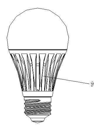
[0030] The wick cover 6 covered with a remote phosphor layer on the inner surface is covered on the blue LED lamp 7, and the combination of the two is used for fluorescent excitation, which replaces the original method of directly covering the blue LED lamp 7 with the phosphor layer, and improves the performance of the LED bulb. The color rendering index and luminous efficiency can reduce the light decay phenomenon caused by traditional LED bulbs and prolong the service life of LED bulbs; the outer surface of the lamp body 4 is uniformly provided with a number of longitudinally opened heat dissipation grooves 9, which increas...


PUM


Abstract

The invention discloses an LED lamp wick module and an LED bulb with the same. The LED lamp wick module comprises a base plate and a lamp wick cover arranged on the base plate in a sleeved mode. At least one blue light LED lamp is arranged on the base plate. A fluorescent powder layer covers the inner surface of the lamp wick cover. The LED bulb comprises an outer shell which comprises a lamp cover and a lamp body which are connected with each other. The LED bulb further comprises the LED lamp wick module arranged in the outer shell. A plurality of radiating grooves are evenly formed in the outer surface of the lamp body. According to the LED lamp wick module and the LED bulb with the same, light declining caused by fluorescent powder can be lowered, long service life can be achieved, and the LED bulb can have good radiating effect.

Description

technical field [0001] The invention relates to the field of lighting technology, in particular to an LED wick module and an LED bulb using the LED wick module. Background technique [0002] With the development of economy and progress of society, energy conservation has become an inevitable and social consensus. Among them, LED bulbs, as environmentally friendly and energy-saving green lighting, are booming in the lighting industry. The current LED light bulbs, in order to obtain soft white light suitable for lighting, generally directly coat phosphor powder on the surface of the blue LED light. Long-term exposure to the heat of the lamp substrate causes the light decay of the LED bulb, that is, the light intensity of the LED bulb is reduced, and the service life of the LED bulb is reduced. Contents of the invention [0003] The object of the present invention is to provide an LED wick module with a longer service life and an LED light bulb using the LED wick module to ...

Claims


Application Information

Patent Timeline
Patent Type & Authority Applications(China)
IPC IPC(8): F21S2/00F21V9/08F21V29/00F21Y101/02F21K9/232F21V29/50F21V29/83F21Y115/10
Inventor 梁月山
Owner KUSN KAIWEI ELECTRONICS
Why Eureka
Try Eureka