
Light-emitting device and projecting system

A light-emitting device and excitation light technology, applied in the optical field, can solve the problems of large color deviation, loss of energy, low energy conversion efficiency of wavelength conversion materials, etc., and achieve the effect of high color rendering index

Active Publication Date: 2012-07-04
APPOTRONICS CORP LTD
View PDF5 Cites 26 Cited by
  • Summary
  • Abstract
  • Description
  • Claims
  • Application Information

AI Technical Summary

Problems solved by technology

[0009] To sum up, there are problems in the above two ways of obtaining monochromatic laser light: the advantage of directly using the wavelength conversion material layer of the corresponding color to generate monochromatic laser light is that the color of the laser light is close to the satisfactory color, so there is no need to modify Satisfactory monochromatic color can be obtained by filtering by laser light; even if filtering is required, the energy loss of filtered light is not large; but the disadvantage is that the energy conversion efficiency of the corresponding color wavelength conversion material is too low
The problem with using wavelength conversion material layers corresponding to other colors with higher efficiency is that due to the large color deviation, most of the energy will be lost in the subsequent filtering process, and the luminous flux of the finally filtered monochromatic light cannot be impressive. satisfy

Method used


Image

  • Light-emitting device and projecting system
  • Light-emitting device and projecting system
  • Light-emitting device and projecting system

Examples


Embodiment Construction

[0033] According to the data in the background technology, it is deduced according to common sense that the two methods for generating monochromatic stimulated light are not satisfactory, so the use of the two methods together will not help to improve the brightness of monochromatic light. However, the inventors have found through experiments that the monochromatic light output with larger luminous flux can be obtained by using two kinds of wavelength conversion materials together. Based on the inventor's experimental data, the present invention proposes a light-emitting device to solve the problem of low luminous flux of the wavelength conversion material layer for stimulated emission of monochromatic light.

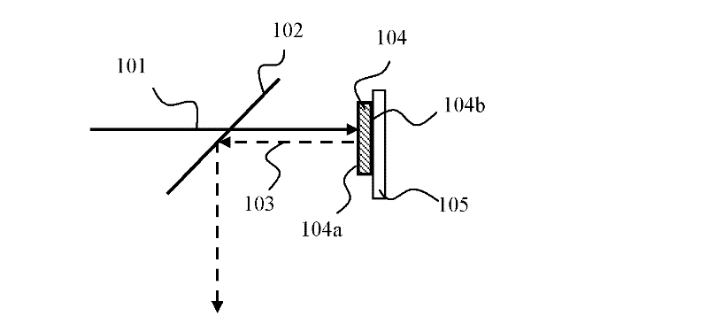
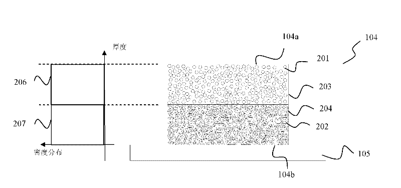
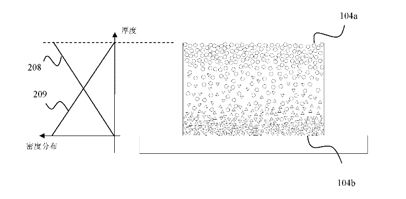
[0034] A light-emitting device proposed by the present invention has an optical structure such as figure 1 shown. The light-emitting device includes an excitation light source (not shown in the figure) for emitting excitation light 101 ; a first wavelength conversion ...


PUM


Abstract

The invention discloses a light-emitting device and a projecting system. The light-emitting device comprises a first wavelength converting material layer which is used for absorbing laser light and emitting mixed stimulated light, wherein the first wavelength converting material layer comprises a first face and a second face which are opposite; the first face is used for receiving exciting light; the light-emitting device additionally comprises a first wavelength converting material which is used for absorbing the exciting light and producing first stimulated light, and a second wavelength converting material which is used for receiving at least part of the first stimulated light and producing second stimulated light; the energy transformation efficiency of the first wavelength converting material is higher than that of the second wavelength converting material; and the light-emitting device also comprises an optical film which is positioned on one side of the second face close to the first wavelength converting material layer and is used for reflecting the first stimulated light and the second stimulated light from the first wavelength converting material layer. Compared with a light-emitting device separately using the first or the second wavelength converting material, the light-emitting device disclosed by the invention can obtain higher luminous flux of monochromatic light.

Description

technical field [0001] The invention relates to the field of optical technology, in particular to a light source device and a projection device. Background technique [0002] At present, the white light source used in projectors is mainly UHP (Ultra High Pressure, ultra-high pressure mercury lamp) bulb, which has high brightness, but its lifespan is only 3000 hours, and the replacement of the lamp is expensive, so it cannot meet the needs of long-term use. [0003] The use of semiconductor light sources to replace UHP bulbs is an important technological development direction. However, among semiconductor light sources, the low efficiency of green light sources has become a major bottleneck. To overcome this problem, it has been proposed to use blue or ultraviolet semiconductor light sources to excite monochromatic wavelength conversion materials to generate monochromatic light. [0004] Chinese patent 200810065225 discloses a method for generating high-brightness fluoresce...

Claims


Application Information

Patent Timeline
IPC IPC(8): G03B21/00G03B21/20G03B21/14F21V13/00F21V9/40
CPCF21V9/10G03B21/20G03B21/204G03B21/00
Inventor 李屹许颜正张利利胡飞
Owner APPOTRONICS CORP LTD
Learn More