Phosphor-nanoparticle combinations

a technology of phosphor and nanoparticles, applied in the field of lighting devices, can solve the problems of inability to generate “white” light, which is required for a very large portion of the lighting industry, and the inability to use a conventional led, etc., and achieve the effects of improving the optical properties, controlling color, and improving the choi

Inactive Publication Date: 2013-02-07
YISSUM RES DEV CO OF THE HEBREWUNIVERSITY OF JERUSALEM LTD +1
View PDF2 Cites 27 Cited by
  • Summary
  • Abstract
  • Description
  • Claims
  • Application Information

AI Technical Summary

Benefits of technology

[0014]The inventors have found that SNPs in general and RSNPs in particular have superior optical properties which render them a much better choice for combining with phosphors in lighting applications. Specifically, the inventors have found that using a phosphor-SNP and phosphor-RSNP combinations of the invention, re-absorption effects of the phosphor emission by the SNP and self absorption of the SNP emission by SNP are small, leading to controlled color and high efficiency. In addition, in combinations containing phosphor-SNP clusters, and high loading, FRET and its undesired consequences are suppressed. RSNPs have very low photoluminescence (PL) self-absorbance and also small absorbance of the phosphor emission and thus are more energy efficient, especially in optically dense layers. A phosphor-SNP and phosphor-RSNP combination of the invention has low self absorption and re-absorption.
[0018]The modulation of the LED emission spectrum may be for illumination purposes, in order to produce broad-spectrum colour output light, for example “white” light, having a high colour rendering index (CRI) and the desired correlated colour temperature (CCT). The broad-spectrum colour output light is produced by converting some of the original light generated by the LED into longer wavelength light. Adding power or intensity to Red is important for obtaining “warmer” light with lower CCT (e.g. 2700-3500K), but “smoothing” specific regions in the spectrum such in the transition from blue to green can also improve the CRI. The modulation of the LED illumination may also be used for optical display purposes. The invented lighting conversion materials are also of use in agricultural applications of specific lighting demands and other areas of applications of lighting.

Problems solved by technology

However, “white” light, which is required for a very large portion of the lighting industry, cannot be generated using a conventional LED.
However, such white light is almost always non-ideal and has in many cases undesired or unpleasant characteristics which may require improvement or correction.
The solution of using three or more different LED is expensive and complicated for some applications.
Unfortunately, a lamp designer does not have an arbitrary set of phosphors from which to choose.
There are a limited number of conventional phosphors containing rare-earth elements that have sufficient light conversion efficiencies.
The emission spectrum of these phosphors is not easily changed.
Furthermore, the spectra are less than ideal in that the light emitted as a function of wavelength is not constant.
Hence, even by combining several phosphors, an optimum white light source is not obtained.
QD additives can offer improvement, but they suffer from high self absorbance, i.e. they absorb light that is emitted when excited.
This lowers their total energy efficiency as light convertors.
Moreover and most significantly, the QD also re-absorbs the phosphor emission, which reduces the energetic efficiency and also shifts the output spectrum such that rational color planning is very difficult.
The efficiency of the FRET process is very sensitive to distance.
FRET leads to colour change (red shift) and losses in the efficiency of light conversion.

Method used


Image

  • Phosphor-nanoparticle combinations
  • Phosphor-nanoparticle combinations
  • Phosphor-nanoparticle combinations

Examples


example 1

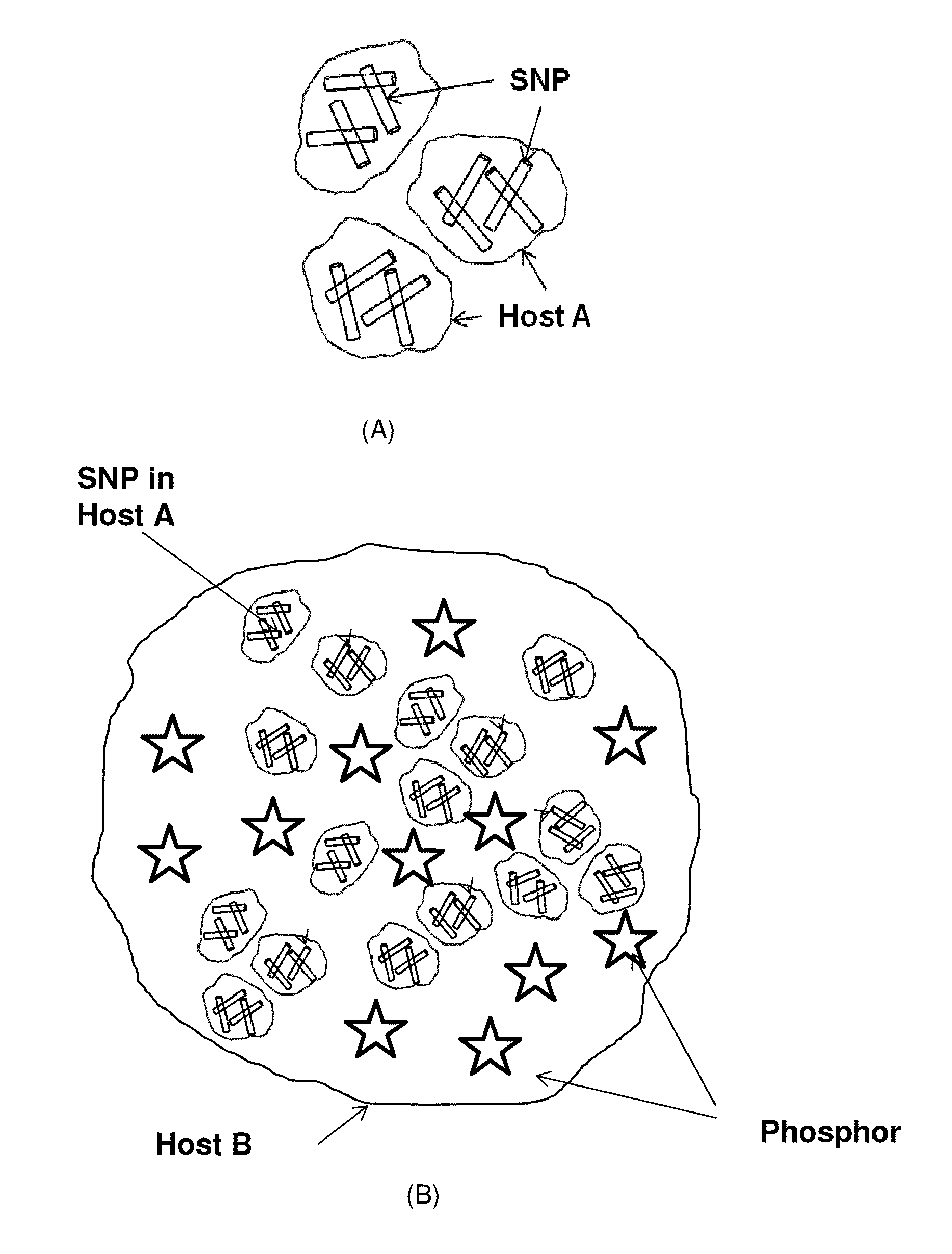
Phosphor—RSNP Combination in Silicone

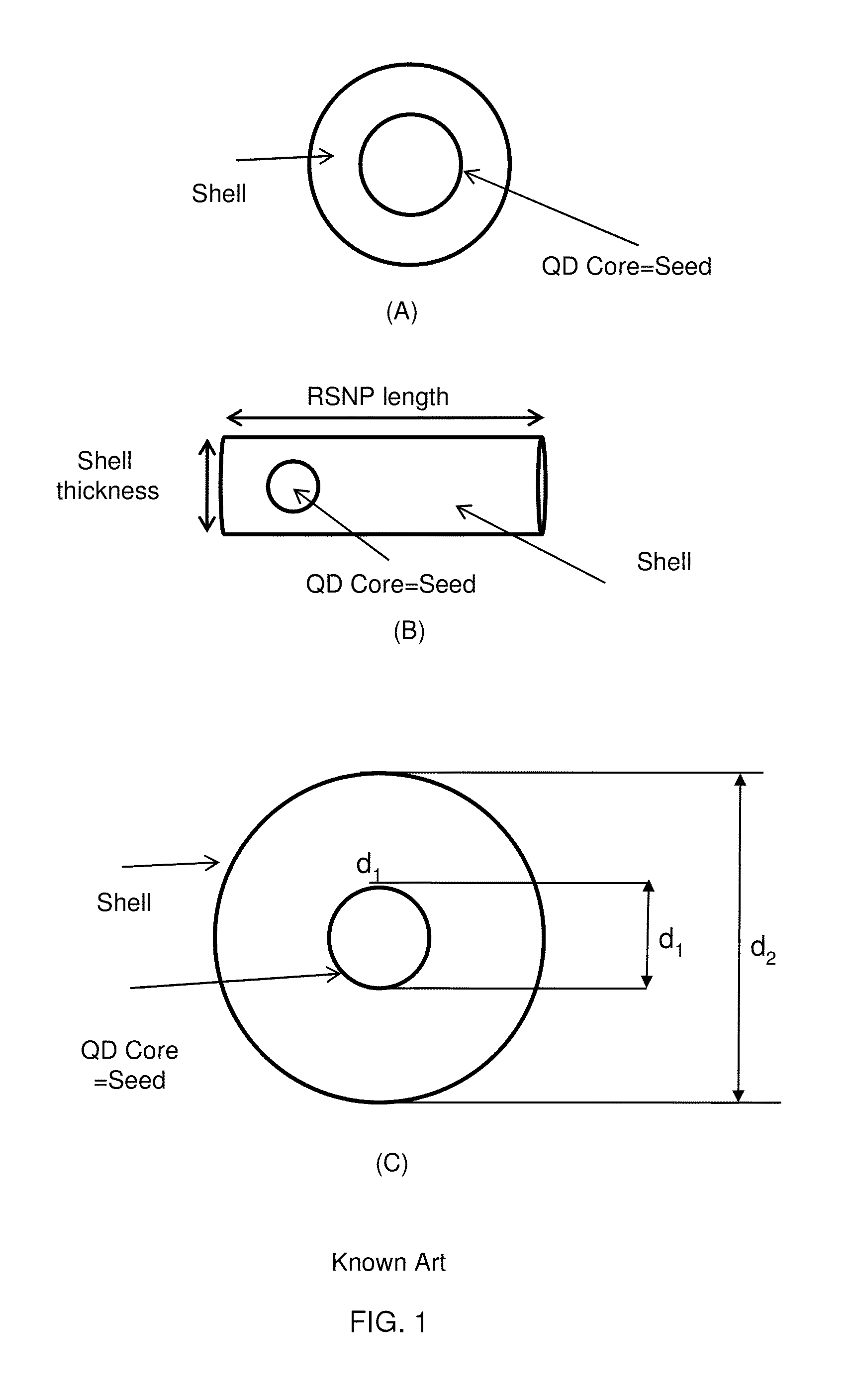
[0045]35×5.6 nm CdSe / CdS RSNPs emitting at 638 nm were first prepared using a procedure similar to that described in L. Carbone et al. “Synthesis and Micrometer-Scale Assembly of Colloidal CdSe / CdS Nanorods Prepared by a Seeded Growth Approach” Nano Letters, 2007, 7 (10), pp 2942-2950. 0.5 g of RTV615A (Momentive, 22 Corporate Woods Boulevard, Albany, N.Y. 12211 USA) was stirred with 0.15 g of RTV615B for 10 minutes. 4.0 mg of the RSNPs were dissolved in 0.4 ml Toluene. 615 mg of yellow phosphor (BYW01A, PhosphorTech, 351 Thornton Rd Ste. 130, Lithia Springs, Ga. 30122, USA) were provided to give a RSNP to Phosphor weight ratio of 4 / 615, i.e. ˜0.65%. The RSNP solution was added to the silicone RTV mixture while stirring. The BYW01A phosphor was then added and the RSNP / phosphor / silicone solution was stirred for 15 minutes. The RSNP / phosphor / silicone solution in then vacuumed until no bubbles were left. The solution was then poured on a glass subst...

example 2

Insertion of RSNP Encapsulated in Polymer into Silicone

[0047]The RSNPs prepared as described in Example 1 were embedded in PVB with 3% loading ratio (weight) and were ground to fine powder. The final powder mean particle size was less than 15 μm. 1.5 g of RTV615A (Momentive, 22 Corporate Woods Boulevard, Albany, N.Y. 12211 USA) was stirred with 0.15 g of RTV615B for 10 min 77 mg of the RSNP / PVB powder was added to the silicone mixture while stirring. 345 mg of Yttrium Aluminum Garnet phosphor (BYW01A, PhosphorTech, 351 Thornton Rd Ste. 130, Lithia Springs, Ga. 30122, USA) were added and the solution was stirred for 15 minutes. The RSNP / phosphor / silicone RTV solution was then vacuumed until no bubbles were left. The solution was then poured on a glass substrate and sandwiched using another glass substrate. 250 μm-thick spacers were positioned between the two glass substrates to obtain the desired film thickness. The sandwiched structure was then placed on a hot plate at 100 C for 1 h...


PUM

PropertyMeasurementUnit
central emission wavelengthaaaaaaaaaa
wavelength rangeaaaaaaaaaa

Abstract

Compositions of matter comprising a seeded semiconductor nanoparticle material and a non-quantum confined phosphor particle material for use in light conversion and light conversion layers comprising such compositions. In various embodiments, spherical core / shell seeded nanoparticles (SNPs) or nanorod seeded nanoparticles (RSNPs) are combined with a phosphor material to provide a composition of matter with small re-absorbance of the phosphor emission in both green and red wavelength regions and small re-absorbance of the SNP emission, In some embodiments, the SNPs or RSNPs are encapsulated in a first host material before being mixed with the phosphor particles. In various embodiments, a SNP / RSNP-phosphor mixture or encapsulated SNP / RSNP-phosphor mixture is incorporated in host matrix.

Description

CROSS REFERENCE TO RELATED APPLICATIONS[0001]This application claims priority from U.S. Provisional Patent Applications No. 61 / 299,018 filed Jan. 28, 2010 and titled “Phosphor-nanoparticle combination” and 61 / 299,012 filed Jan. 28, 2010 and titled “Light source with prescribed color emission”, both of which are incorporated herein by reference in their entirety.FIELD AND BACKGROUND[0002]Embodiments of the invention relate in general to lighting devices which include light conversion materials and in particular to light conversion materials for use in lighting devices comprising light emitting diodes (LEDs), where the conversion materials include combinations of semiconductor nanoparticles and phosphors based on rare-earth elements for light conversion and light conditioning.[0003]LEDs offer significant advantages over incandescent and fluorescent lamps with respect to their high energy efficiency and long lifetimes. LEDs are applicable in diverse applications including displays, aut...

Claims


Application Information

Patent Timeline
Patent Type & Authority Applications(United States)
IPC IPC(8): G02B5/20B82Y30/00
CPCC09K11/02C09K11/565H01L33/505H01L33/502C09K11/883C09K11/7706C09K11/025C09K11/56Y10S977/774Y10S977/779Y10S977/95B82Y20/00
Inventor ARBELL, HAGAIAHARONI, ASSAFBANIN, URI
Owner YISSUM RES DEV CO OF THE HEBREWUNIVERSITY OF JERUSALEM LTD
Why Eureka
Try Eureka