Projection optical system, manufacturing method thereof, and projection exposure apparatus

a technology of projection optical system and manufacturing method, applied in the field of projection optical system, can solve the problems of chromatic aberration, limited use of glass materials that can be used under current conditions, and difficulty in putting projection optical system into practical use with a refractive system

Inactive Publication Date: 2002-04-18
NIKON CORP
View PDF0 Cites 101 Cited by
  • Summary
  • Abstract
  • Description
  • Claims
  • Application Information

AI Technical Summary

Problems solved by technology

In particular, when the exposure light wavelength becomes vacuum ultraviolet VUV), approximately 200 nm or shorter, the glass materials that can be used under current conditions becomes limited to, for example, synthetic silica, fluorite (CaF.sub.2), and magnesium fluoride (MgF.sub.2).
The problem of how to compensate chromatic aberration therefore happens.
However, when he exposure light wavelength fall to 180 nm or shorter as with an F.sub.2 laser (wavelength 157 nm), it is difficult to put projection optical systems into practical use with a refractive system, but expectations are rising for catadioptric systems providing a reflective member as means for compensating chromatic aberration.
Of these, optical systems that form an intermediate image partway through the optical system, for example, such as the optical system disclosed in U.S. Pat. No. 5,650,877, are quite effective in terms of throughput and ease in manufacturing in comparison with optical systems that have an optical member such as a semi-transparent mirror disposed partway, and therefore have no intermediate image formed, greatly reduced light intensity, and increased danger of large-scale flares developing.
However, with the catadioptric optical system, even if a virtually upright cylinder, the entire length is quite long in comparison with a refractive system, and becomes difficult to support with a single lens barrel.
In such cases, if a single lens-barrel with a relatively small refractive member and a relatively large reflective member are supported as a single body, the configuration of that lens barrel becomes complicated, and the stable support of that lens barrel becomes difficult, Moreover, there are problems with production costs becoming high with projection optical systems since it takes time to perform the assembly adjustment of that lens barrel and all of the optical elements.
However, in cases where these optical elements are simply divided into a plurality of groups and held by a plurality of divided lens-barrels, there require the divided lens-barrels with partially extremely complex structures, and also, tears are entertained as to complex processes of assembly adjustment such as aligning the respective axes of each divided lens-barrel to each other.
Furthermore, since there is a danger of the positional relationship between optical elements that are held by different divided lens-barrels fluctuating relative to set values by simply holding a plurality of divided lens-barrels, there is a danger of an increase in contributing factors for the development of aberrations.
Moreover, in the projection exposure apparatus using vacuum ultraviolet light having wavelengths of approximately 200 nm or less as exposure light, when a purge gas is flowed through the optical path inside of projection optical systems, if those lens barrels are configured from a plurality of divided lens-barrels, then stagnancy develops in the flow of purge gas at the boundaries of the divided lens-barrels, and there is a danger that the density of light absorbing substances, such as oxygen, may not sufficiently decrease.
In particular, in a projection exposure apparatus using light of a wavelength of 170 nm or shorter, for example F.sub.2 laser light (157 nm wavelength) as exposure light, since the permissible value of the residual density of the light absorbing substances is lowered, if a divided lens-barrel type is simply adopted, there is a danger that the residual density of the light absorbing substances may not fall below the permissible value,
When the position of the reflecting members is off a designed position, a large aberration compared to the reflective member occurs.

Method used


Image

  • Projection optical system, manufacturing method thereof, and projection exposure apparatus
  • Projection optical system, manufacturing method thereof, and projection exposure apparatus
  • Projection optical system, manufacturing method thereof, and projection exposure apparatus

Examples


first embodiment

[0066] In the following, the present invention is described while referencing FIG. 2 to FIG. 4. This embodiment employs an F.sub.2 laser (center wavelength of 157. 6 nm) as an exposure light illumination light) and is applied to the invention onto an upright cylindrical-shaped catadioptric projection optical system with a reflective mirror that has two apertures respectively formed near the optical axes.

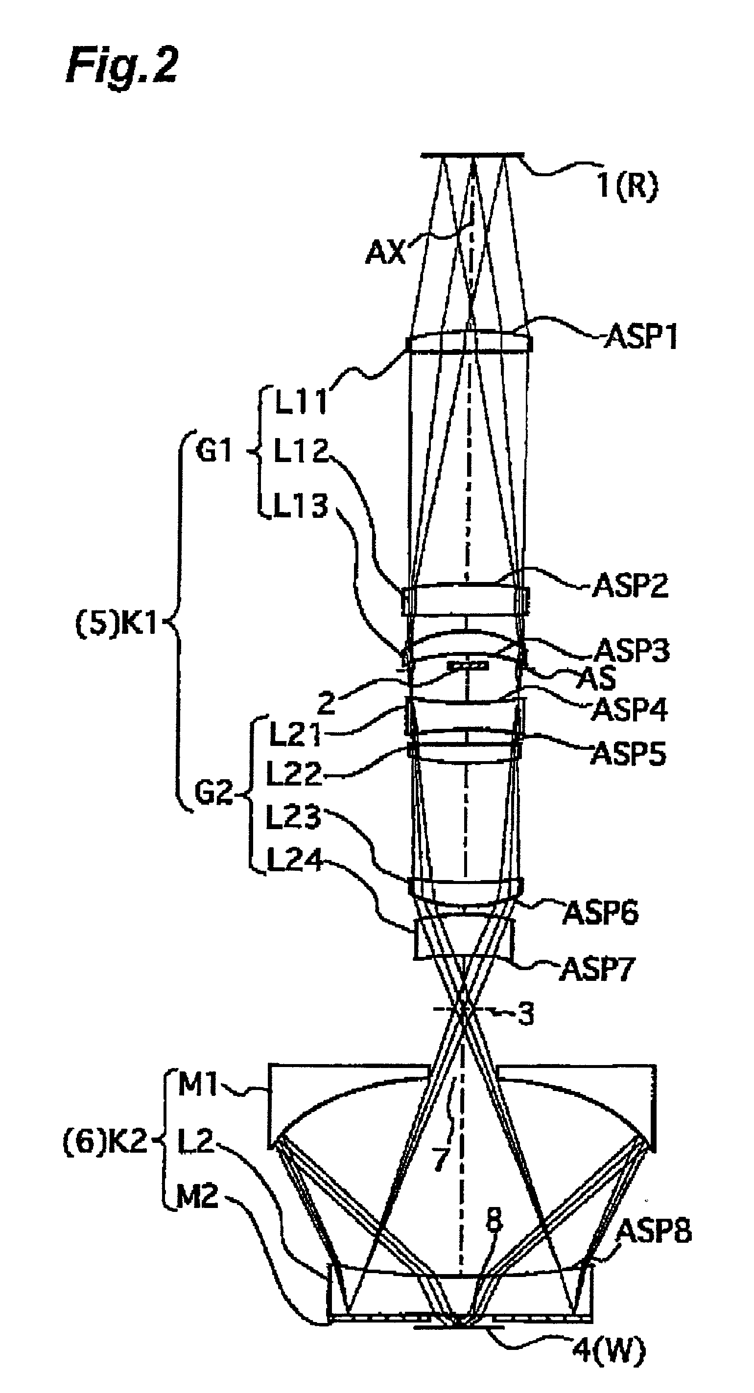
[0067] FIG. 2 is a lens block diagram of a projection optical system according to this embodiment. In FIG. 2, an image of an object disposed in object plane 1 first plane) is formed on image plane 4 (second plane) by the projection optical system of this embodiment with a predetermined projection magnification .beta. (lateral magnification). Projection magnification .beta. of this embodiment is 1 / 4.times.. During exposure, the pattern surface of the reticle R, which is used as a mask, is disposed in the object plane, and the surface of the wafer W (glass plate, etc.), which is used a...

second embodiment

[SECOND EMBODIMENT]

[0102] Next, a projection optical system according to the second embodiment of the present invention is described while referencing FIG. 1 and FIGS. 5 to 7. This embodiment employs an F.sub.2 laser (central wavelength of 157.6 nm) as the exposure light and is used in the present invention onto an upright cylindrical catadioptric projection optical system including two reflective mirrors, the respective apertures thereof formed along each of the two optical axes. In FIGS. 5 to 7, the portions corresponding to those of FIGS. 2 and 3, are assigned the same or similar reference mark and their detailed description is omitted.

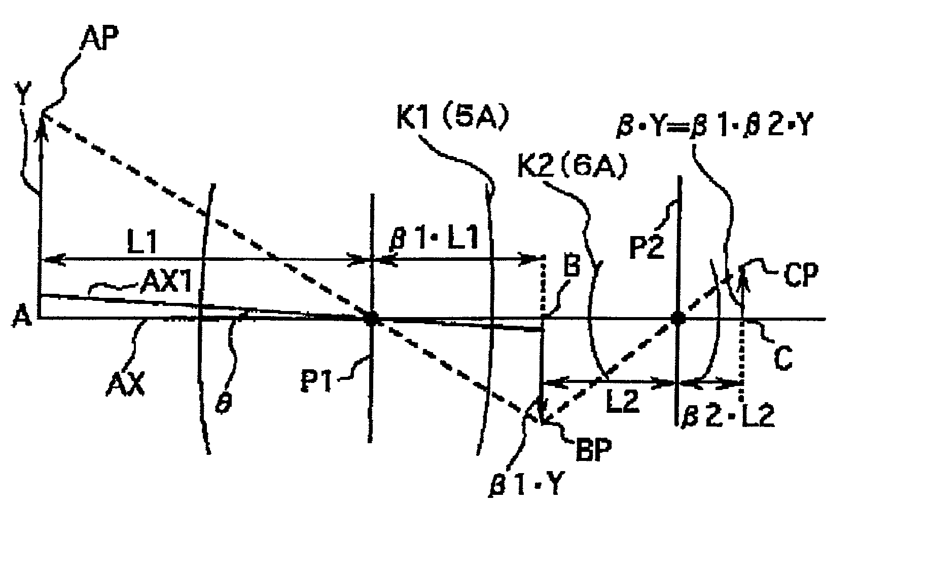
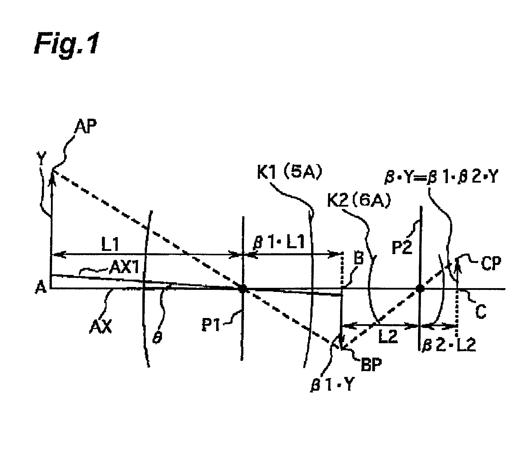
[0103] FIG. 1 is a schematic view of the projection optical system of this second embodiment. In FIG. 1; the projection optical system of this embodiment comprises a first imaging optical system K1 and a second imaging optical system K2; wherein a light from object point AP, which is located at height Y of a position A on an optical axis AX, passes...

third embodiment

[THIRD EMBODIMENT]

[0127] The third embodiment of the projection optical system according to the present invention is described using FIGS. 8 and 9. In the third embodiment, the present invention is applied to the off-axis catadioptric type (a light passes through the outside of the predetermined reflecting mirror) projection optical system, which uses the ArF excimer laser (central wavelength: 193.3 nm) is used as the exposure light. For the parts in FIGS. 8 and 9 corresponding to the parts in FIGS. 2 through 6, the same or similar reference numerals and detailed descriptions are omitted.

[0128] FIG. 8 is a block diagram of the lens of the catadioptric type projection optical system in this embodiment. In FIG. 8, the projection optical system of this embodiment comprises: a catadioptric type first imaging optical system G1, which forms intermediate image I1 of reticle R pattern on the object plane (the first plane); and dioptric type second imaging optical system G2, which forms the ...


PUM

PropertyMeasurementUnit
wavelengthsaaaaaaaaaa
wavelengthaaaaaaaaaa

Abstract

A projection optical system forming an image of an object in a first plane onto a second plane, comprising, an optical element group including at least one refractive member and a plurality of reflective members, and a plurality of lens-barrel units holding the optical element group divided into a plurality of groupings, wherein the plurality of reflective members is all held by one lens-barrel unit of the plurality of lens-barrels units.

Description

[0001] 1. Field of the Invention[0002] The present invention relates to a projection optical system, for example, provided in a projection exposure apparatus that is used on occasion of photolithography when manufacturing semiconductor elements, display elements such as liquid crystal display and plasma display, and micromachine etc. such as microdevices. It also relates to a manufacturing method of the projection optical system and to a projection exposure apparatus,[0003] 2. Related Background Art[0004] In a photolithographic process used for manufacturing semiconductor elements and the like, projection exposure apparatus is used to expose, through a projection optical system, the image of the pattern of the reticle as mask onto a substrate, i.e. a wafer (or glass plate, etch) on which is applied a photo resist. As the degree of integration of semiconductor elements and so on continue to improve, demand for a resolving power of the projection optical system in a projection exposur...

Claims


Application Information

Patent Timeline
Patent Type & Authority Applications(United States)
IPC IPC(8): G02B7/02G02B13/00G02B13/14G02B17/08G02B27/18G03F7/20H01L21/027
CPCG02B13/143G02B17/0808G03F7/70225G02B17/0892G02B27/18G02B17/0856
Inventor TAKAHASHI, TETSUONISHIKAWA, JINOMURA, YASUHIRO
Owner NIKON CORP
Why Eureka
Try Eureka