
Display apparatus and driving method for the same

a technology of display apparatus and driving method, which is applied in the field of flat display apparatus, can solve the problems that the technology of improving the lifetime according to the above-described documents has not yet been put to practical use, and achieve the effects of increasing the average luminance of the screen, and efficient prolonging the life of the light-emitting elemen

Active Publication Date: 2006-01-26
JOLED INC
View PDF8 Cites 34 Cited by
  • Summary
  • Abstract
  • Description
  • Claims
  • Application Information

AI Technical Summary

Benefits of technology

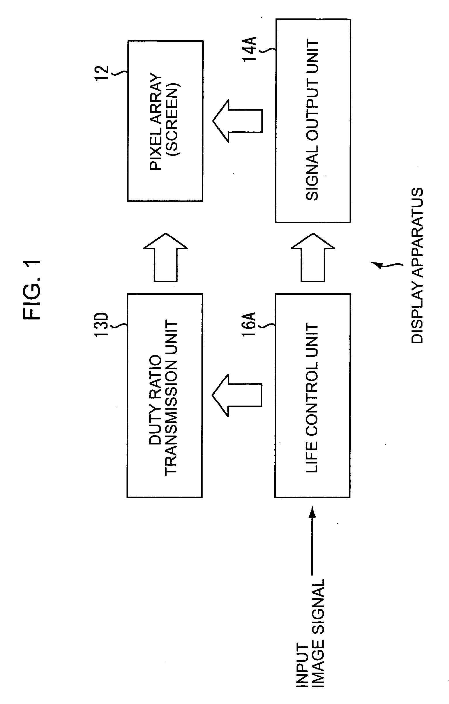
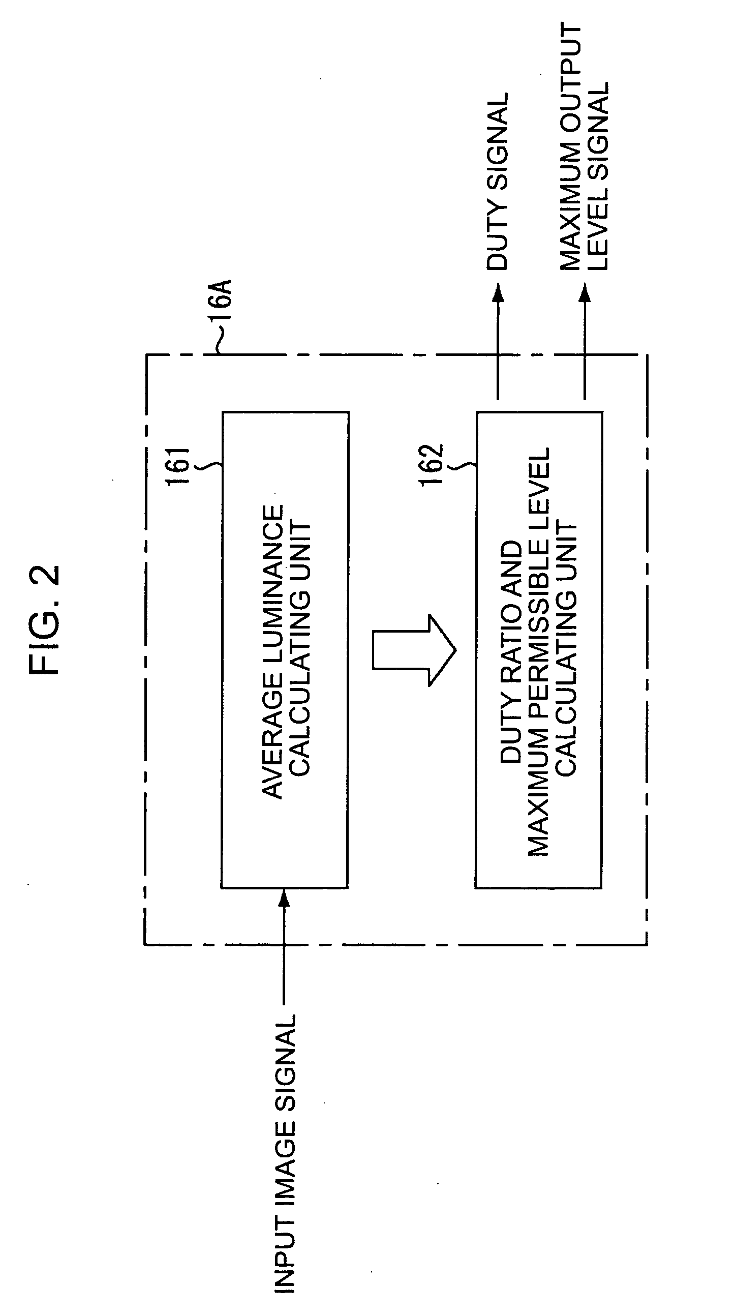
[0012] The technologies for improving the lifetime according to the above-described documents have not yet been put to practical use and must be improved more. A flat display apparatus according to an embodiment of the present invention has taken into consideration the above-described problems of known display apparatuses and is capable of extending the life of pixels of light-emitting elements constituting the display apparatus by improving the circuitry. The life of light-emitting elements is extended as described below. The display apparatus according to an embodiment of the present invention includes a pixel array, a life control unit, a signal output unit, and a duty ratio transmission unit. The pixel array includes a plurality of pixels of light-emitting elements constituting a screen. The pixel array is configured to display each frame of an image on the screen by emitting light having a luminance in accordance with the level of an image signal and to continuously emit light from the screen within each frame for an amount of time specified by a duty ratio. The life control unit is configured to extend the life of the light-emitting elements by simultaneously adjusting the maximum permissible level of the image signal and the duty ratio. The signal output unit is configured to drive the screen to display an image by outputting an image signal adjusted within the maximum permissible level to the pixel array. The duty ratio transmission unit is configured to enable the screen to emit light for an amount of time specified by transmitting an adjusted duty ratio to the pixel array.
[0014] A method for driving a display apparatus according to an embodiment of the present invention is described below. The method for driving a display apparatus has a plurality of pixels of light-emitting elements constituting a screen to display each frame of an image on the screen by emitting light having a luminance in accordance with a level of an image signal and to continuously emit light from the screen within each frame for an amount of time specified by a duty ratio. The method includes the steps of extending the life of the light-emitting elements by simultaneously adjusting the maximum permissible level of the image signal and the duty ratio, displaying an image by outputting an image signal adjusted within the maximum permissible level to the plurality of pixels, and enabling the screen to emit light for an amount of time specified by transmitting an adjusted duty ratio to the plurality of pixels.
[0015] The principle of extending the life of the light-emitting element according to an embodiment of the present invention is to variably suppress the amount of light emitted from the light-emitting element when the amount of light emitted from the light-emitting element per frame is large. When the average luminance of the screen is high, the quality of the image will not be affected even if the amount of light emitted from the light-emitting element is decreased. Therefore, the life of the light-emitting element can be extended by decreasing the amount of light emitted from the light-emitting element.
[0017] On the other hand, for the light-emitting element according to an embodiment of the present invention, in addition to the amount of time light is emitted per frame, the intensity of the emitted light is controlled so as to extend the life of the light-emitting element. In other words, when the screen is bright, the amount of time light is emitted per frame and the intensity of the emitted light are both controlled to efficiently extend the life of the light-emitting element. For this reason, the duty ratio specifying the amount of time light is emitted per frame and the maximum permissible level of the image signal are reduced more as the average luminance of the screen increases. The intensity of the emitted light has a greater effect on the life of the light-emitting element than the amount of time light is emitted. Hence, for the light-emitting element according to an embodiment of the present invention, to suppress the amount of light emitted, unlike a known light-emitting element, both the amount of time light is emitted and the intensity of the emitted light are reduced. In this way, the life of the light-emitting element is extended while the effect of the amount of time the light is emitted is reduced and the effect of the intensity of the emitted light is increased.
[0018] The life control function according to an embodiment of the present invention may be included in a display apparatus by including the life control function in an integrated circuit (IC) of, for example, a timing generator constituting a part of a system. In this way, the life control function according to an embodiment of the present invention can be realized without any special peripheral circuits and without affecting the existing display system. Accordingly, the life of the light-emitting element can be significantly improved by a relatively small change in the circuitry.

Problems solved by technology

The technologies for improving the lifetime according to the above-described documents have not yet been put to practical use and must be improved more.

Method used


Image

  • Display apparatus and driving method for the same
  • Display apparatus and driving method for the same
  • Display apparatus and driving method for the same

Examples


Embodiment Construction

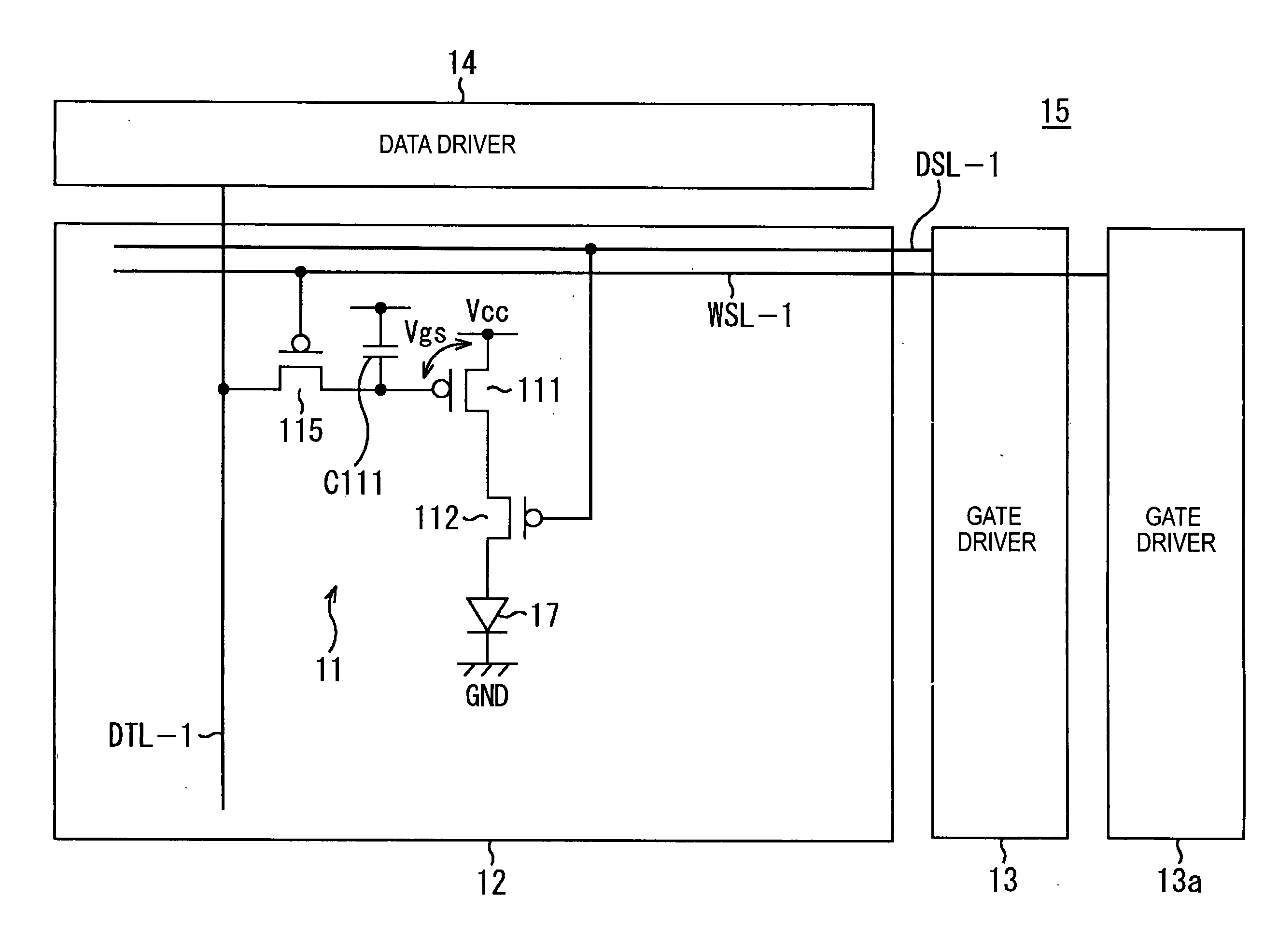
[0031] Embodiments of the present invention will be described in detail with reference to the drawings. FIG. 1 is a functional block diagram of a display apparatus according to an embodiment of the present invention. As illustrated in the drawing, the display apparatus includes a pixel array 12, a life control unit 16A, a duty ratio transmission unit 13D, and a signal output unit 14A. The pixel array 12 is a screen constituted of a group of pixels including light-emitting elements, such as organic EL elements. The pixel array 12 emits light having luminance in accordance with the level of an image signal so as to display an image for each frame. At the same time, the pixel array 12 continues to emit light from the screen within each frame for an amount of time specified by a duty ratio. The life control unit 16A adjusts the maximum permissible level of an image signal and the duty ratio so as to extend the life of each light-emitting element included in the pixel array 12. The signa...


PUM


Abstract

A display apparatus includes a pixel array, a life control unit, a signal output unit, and a duty ratio transmission unit. The pixel array, including light-emitting elements constituting a screen, displays each frame of an image on the screen by emitting light having a luminance in accordance with a level of an image signal and continuously emits light from the screen within each frame for an amount of time specified by a duty ratio. The life control unit extends the life of the light-emitting elements by simultaneously adjusting the maximum permissible level of the image signal and the duty ratio. The signal output unit drives the screen to display an image by outputting an image signal adjusted within the maximum permissible level to the pixel array. The duty ratio transmission unit for enabling the screen to emit light for an amount of time specified transmitting an adjusted duty ratio to the pixel array.

Description

CROSS REFERENCES TO RELATED APPLICATIONS [0001] The present invention contains subject matter related to Japanese Patent Application JP 2004-215086 filed in the Japanese Patent Office on Jul. 23, 2004, the entire contents of which are incorporated herein by reference. BACKGROUND OF THE INVENTION [0002] 1. Field of the Invention [0003] The present invention relates to a flat display apparatus including a screen constituted of a group of light-emitting elements, such as organic electroluminescent (EL) elements. More specifically, the present invention relates to a technology for extending the light emission life of the light-emitting elements by suppressing degradation that occurs over time by improving the circuitry of the light-emitting elements. [0004] 2. Description of the Related Art [0005] A popular flat panel display apparatus under development, such as an organic electroluminescent (EL) display, is constituted of pixels including light-emitting elements. An organic EL display ...

Claims


Application Information

Patent Timeline
IPC IPC(8): G09G3/10
CPCG09G3/3233G09G3/3291G09G2300/0861G09G2360/16G09G2320/048G09G2320/0626G09G2320/0271
Inventor TADA, MITSURUYAMAMOTO, TETSURO
Owner JOLED INC
Learn More