Driving apparatus of H bridge circuit and protection method of the same

Inactive Publication Date: 2005-08-18
DENSO CORP
View PDF13 Cites 34 Cited by
  • Summary
  • Abstract
  • Description
  • Claims
  • Application Information

AI Technical Summary

Benefits of technology

[0014] In accordance with a driving apparatus for an H bridge circuit according to a seventh aspect, a first switching device, a second switching device and the driving device provided on the side of the power supply are put in an electrically conductive state in the event of a detected over-voltage. In this state, an electric potential appearing at the gate of the P-channel MOSFET is firmly set at a cut-off level lower than the over-voltage applied to the power supply by a difference equal to a voltage drop, which is caused by the electrical conductions of the second switching device and the driving device provided on the side of the power supply. Thus, the P-channel MOSFET is put in an electrically non-conductive state with a high degree of reliability.
[0015] In addition, when an over-voltage

Problems solved by technology

However, a power transistor having a high withstand voltage is built in a chip having a large size, which prevents miniaturization.
As a result, the use of such a power transistor is cumbersome.
However, the technology disclosed in patent reference 1 has a configuration in which an abnormality of a motor is detected on the assumption that the voltage of the power supply is normal.
Thus, the technology is not suitable for an application to protect se

Method used


Image

  • Driving apparatus of H bridge circuit and protection method of the same
  • Driving apparatus of H bridge circuit and protection method of the same
  • Driving apparatus of H bridge circuit and protection method of the same

Examples


first embodiment

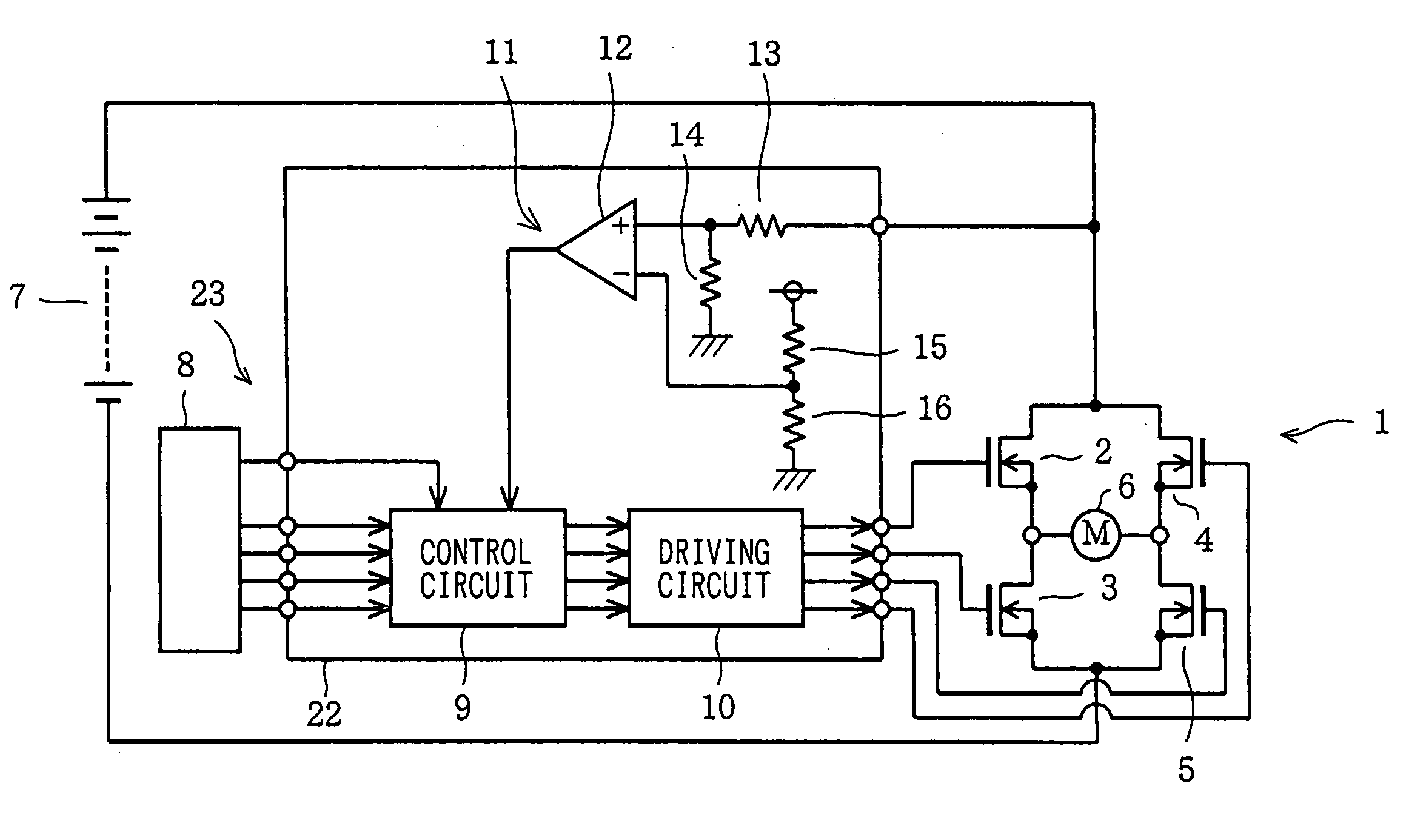
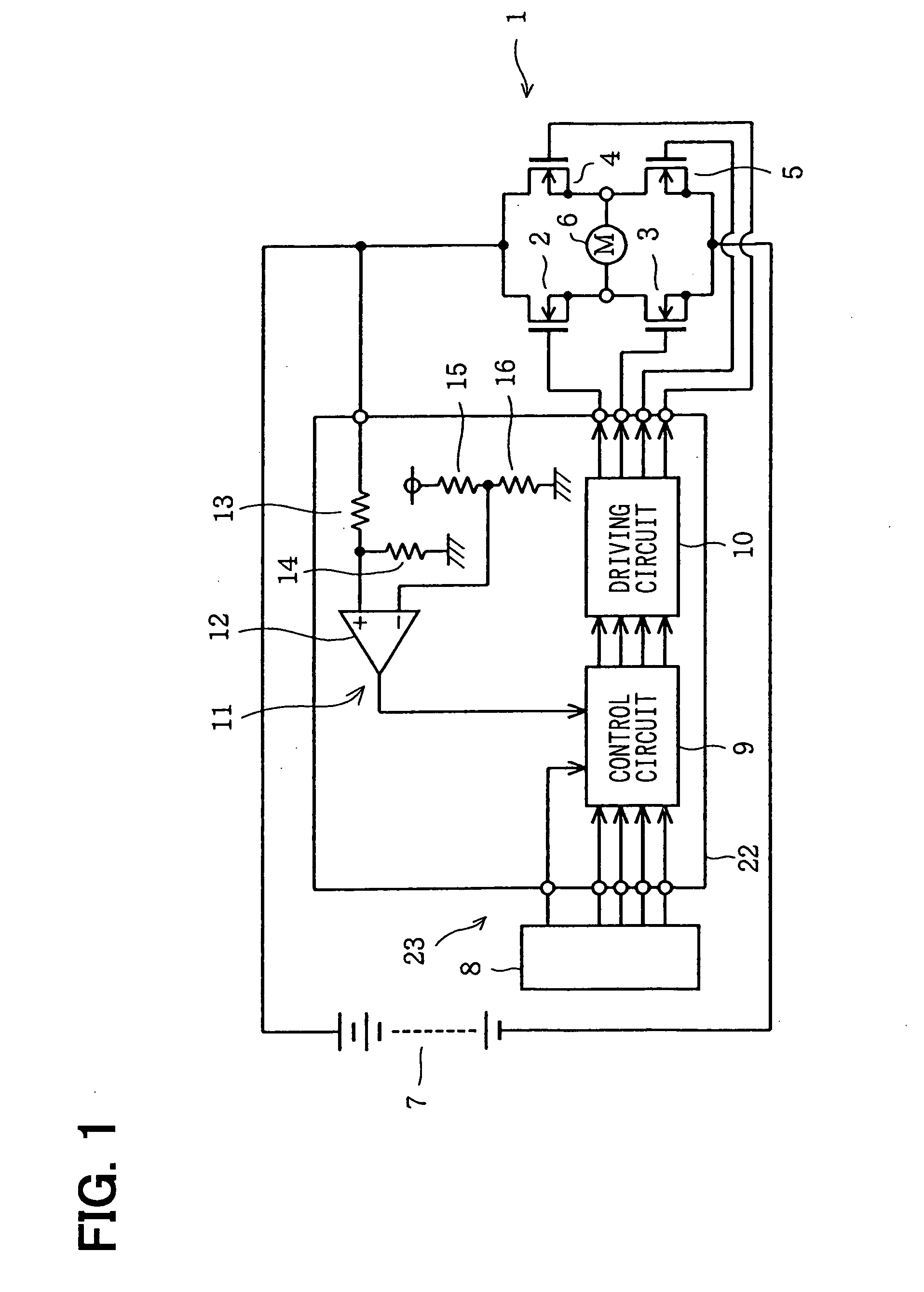
[0037] Referring to FIGS. 1 to 5, a first embodiment implementing of an actuator ECU mounted on a vehicle as, for example, an ECU for driving a DC motor for opening and closing a throttle valve of the engine will be described. FIG. 1 is a diagram showing a configuration including an H bridge circuit 1 and a driving apparatus for driving the H bridge circuit 1. As shown in the figure, the H bridge circuit 1 comprises four N-channel power MOSFETs 2 to 5 wired to each other in a bridge connection. The N-channel power MOSFETs 2 to 5 are each used as a semiconductor switching-device. A DC motor 6 is connected to the H bridge circuit 1 as the load of the H bridge circuit 1. The DC motor 6 outputs a rotation power for opening and closing the throttle valve of the engine. The mechanism for applying the rotation power is not shown in the figures for ease of illustration. As a power supply for supplying power to the H bridge circuit 1, a battery 7 of the vehicle is employed. The battery 7 out...

sixth embodiments

Second to Sixth Embodiments

[0051] FIGS. 6 to 10 are diagrams showing second to sixth embodiments respectively. Only differences from the first embodiment are explained. These embodiments are different from each other in that they employ different types of semiconductor switching-devices in the H bridge circuit.

[0052] In the second embodiment shown in FIG. 6, the H bridge circuit 31 employs four NPN transistors 32 to 35. In the third embodiment shown in FIG. 7, the H bridge circuit 36 employs P-channel MOSFETs 37 and 38 on the side of the power supply as well as N-channel MOSFETs 39 and 40 on the side of the ground.

[0053] In the fourth embodiment shown in FIG. 8, the H bridge circuit 41 employs two PNP transistors 42 and 43 on the side of the power supply as well as two NPN transistors 44 and 45 on the side of the ground. In the fifth embodiment shown in FIG. 9, the H bridge circuit 46 employs N-channel MOSFETs 47 and 48 on the side of the power supply as well as P-channel MOSFETs ...

seventh embodiment

[0055] FIGS. 11 to 13 are diagrams showing a seventh embodiment of the present invention. The seventh embodiment includes the H bridge circuit 36 of the third embodiment shown in FIG. 7 and a concrete configuration of a driving apparatus 61. As described above, the H bridge circuit 36 employs the P-channel MOSFETs 37 and 38 on the side of the power supply. In such a configuration, a charge-pump circuit for a configuration including N-channel MOSFETs on the side of the power supply is not required. Thus, the seventh embodiment has a merit of a simple configuration of the driving circuit. However, in order to put these FETs 37 and 38 in an electrically non-conductive state in case a surge voltage is applied, a voltage having a level close to the surge voltage needs to be supplied to the gates of the FETs 37 and 38. For this reason, the driving apparatus 61 itself must be capable of enduring an applied high voltage and have a circuit configuration capable of putting the FETs 37 and 38 ...


PUM


Abstract

In order to protect semiconductor switching-devices employed in an H bridge circuit against an over-voltage without using a special protection circuit, a control circuit outputs a control signal to a driving circuit for driving the H bridge circuit in order to turn off FETs serving as the semiconductor switching-devices when an over-voltage detection circuit detects the over-voltage applied to the H bridge circuit.

Description

CROSS REFERENCE TO RELATED APPLICATIONS [0001] This application is based upon, claims the benefit of priority of, and incorporates by reference the contents of, Japanese Patent Application No. 2004-38138 filed on Feb. 16, 2004 and Japanese Patent Application No. 2004-331940 filed on Nov. 16, 2004. FIELD OF THE INVENTION [0002] The present invention relates to an apparatus for driving an H bridge circuit and to a method to protect the H bridge circuit. BACKGROUND OF THE INVENTION [0003] Recently, efforts have been made to increase the number of functions in a car and to make the car more luxurious. In order to implement the functions, an actuator such as a motor is provided at every portion of the car. Accordingly, a larger number of actuators are employed. Development of a small-size and low-cost actuator ECU (Electronic Control Unit) capable of controlling a large power to address such a situation is expected. [0004] An H bridge circuit comprising four semiconductor switching-devic...

Claims


Application Information

Patent Timeline
IPC IPC(8): H02P7/28H02H7/08H02P7/00H03K17/06H03K17/082H03K17/10H03K17/687
CPCH02H7/0838H02P7/0044H03K17/063H03K17/6877H03K17/102H03K17/14H03K17/0822H02P7/04
Inventor KASUYA, HIROKAZUNUMAZAKI, KOJISAITOU, MITSUHIROFUKUDA, YUTAKAUEDA, NOBUMASA
Owner DENSO CORP
Why Eureka
Try Eureka