Liquid ejecting device

a liquid ejector and liquid technology, applied in the direction of printing, other printing apparatus, etc., can solve the problems of insufficient supply of ink to the ejector head, long ink path, complex shape of the circulating path, etc., and achieve the effect of improving the ability to remove air bubbles

Inactive Publication Date: 2009-10-01
FUJIFILM CORP
View PDF4 Cites 36 Cited by
  • Summary
  • Abstract
  • Description
  • Claims
  • Application Information

AI Technical Summary

Benefits of technology

[0010]The present invention provides a liquid ejecting device that has an excellent ability to remove air bubbles.
[0012]In accordance with the first aspect, liquid is pressure-fed separately from both directions to the ejecting head. Therefore, even when the flow path of the liquid is complex and is easy for air bubbles to become trapped, the trapped air bubbles can be removed, and the air bubble removing ability improves. Further, the liquid that is pressure-fed is recovered at the degas device and degassed. Therefore, as compared with a case in which ink is ejected and liquid that includes air bubbles is discharged, liquid is not wasted and the amount that is consumed can be suppressed.
[0013]The liquid is pressure-fed from both directions to the ejecting head, by using the two tanks that are the first tank and the second tank. Therefore, sudden changes in pressure can be absorbed, and pressure control also is easy. Further, by using the two pumps that are the first pump and the second pump, pressure with respect to the first and second flow paths is controlled, and pressure that is sufficient for pressure-feeding the liquid can be applied. Moreover, breakage of the ejecting head due to excessive application of pressure can be prevented.
[0015]Air bubbles, that exist at the wall surfaces of the first tank and the second tank such that they stick thereto, are difficult to remove by pressure-feeding a liquid. Accordingly, as in the second aspect of the present invention, air bubbles are supplied to the flow paths, and the liquid that includes the supplied air bubbles is made to flow by the first pump and the second pump such that the supplied air bubbles are degassed at the degas device. Due thereto, the air bubbles that exist not only in the flow paths but also at the wall surfaces of the first tank and the second tank and the like, the supplied air bubbles merge together and become a large air bubble, and the large air bubble is sent to the degas device and degassed. Therefore, even air bubbles that are difficult to remove can be removed, and the air bubble removing ability can be improved.
[0016]As described above, the present invention can remove well the air bubbles that are generated in an ejecting head, and in flow paths through which liquid is fed, and the like.

Problems solved by technology

In inkjet printers, air bubbles that arise at an ejecting head that ejects ink are a cause of non-ejecting of the ink.
In such cases, the flow path resistance increases, and ink cannot be supplied sufficiently to the ejecting head.
Moreover, in the case of a device that uses an elongated ejecting head as the ejecting head, the ink path is long and the shape of the circulating path is complex.
Therefore, the flow path resistance is large, and is difficult to trap and remove the air bubbles.
In pressure-feeding the ink in the one direction, the way that the ink flows within the path is limited, and therefore, there exist air bubbles that cannot be completely captured in light of the structure of the path.
However, this treatment is for the purpose of preventing clogging of the filter, and removal of air bubbles that are within the circulating path cannot be carried out.
Moreover, in the devices disclosed in documents 1 and 4, when removing air bubbles that are within the path, ink is wasted because ink that includes air bubbles is discharged from the nozzles for ink ejection.

Method used


Image

  • Liquid ejecting device
  • Liquid ejecting device
  • Liquid ejecting device

Examples


Embodiment Construction

[0032]An example of an exemplary embodiment of the present invention will be described in detail hereinafter with reference to the drawings.

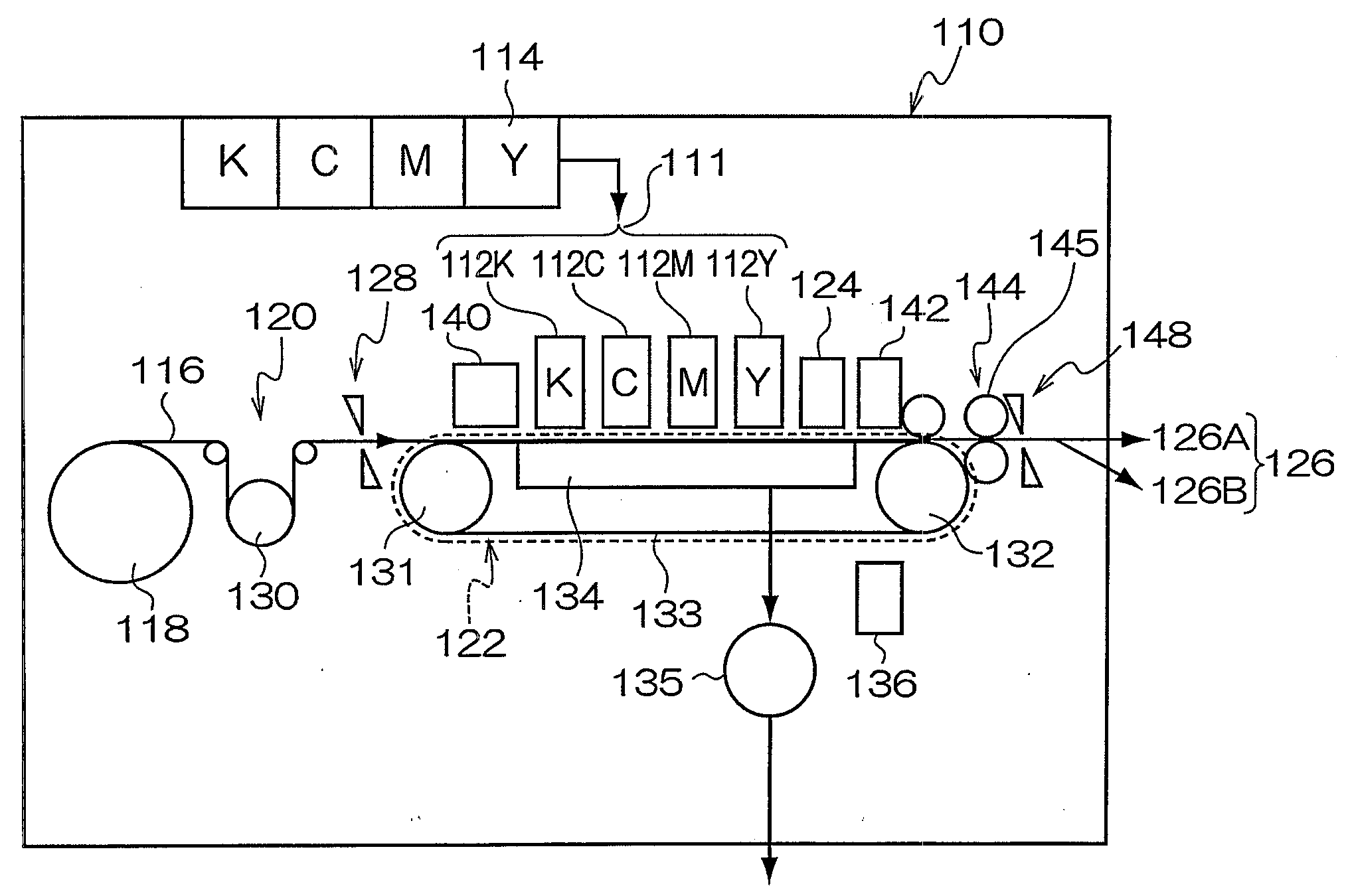
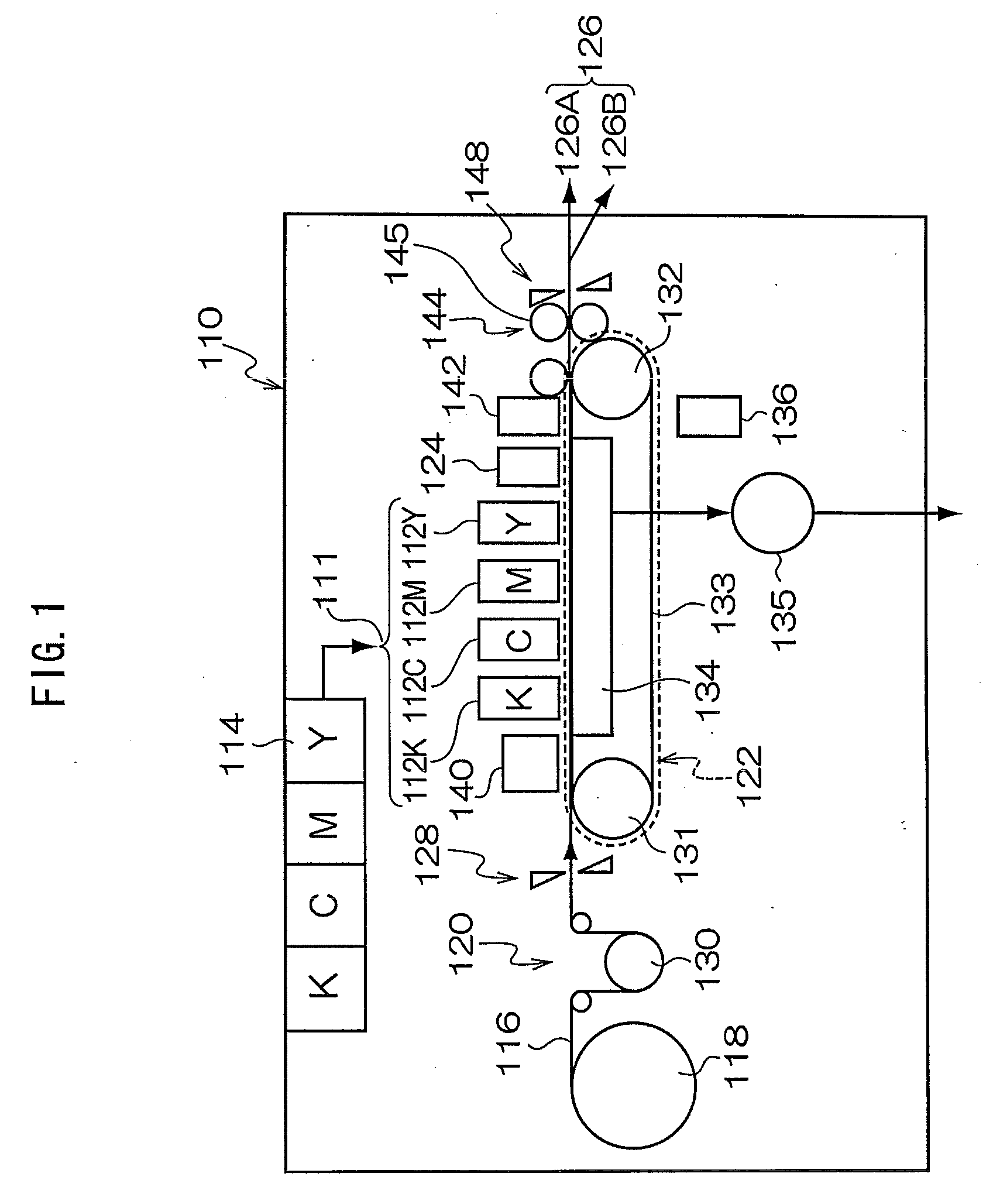
[0033]FIG. 1 is an overall structural drawing of an inkjet recording device showing an exemplary embodiment of a liquid ejecting device relating to the present invention. As shown in FIG. 1, an inkjet recording device 110 includes a printing section 111, an ink storing / loading section 114, a paper feeding section 118, a decurling process section 120, a belt conveying section 122, a print detecting section 124, and a paper discharging section 126. The printing section 111 has plural inkjet recording heads (hereinafter called heads) 112K, 112C, 112M, 112Y that are provided in correspondence with respective inks of black (K), cyan (C), magenta (M) and yellow (Y). The ink storing / loading section 114 stores the inks that are supplied to the respective heads 112K, 112C, 112M, 112Y. The paper feed section feeds recording paper 116 that is a recording m...


PUM


Abstract

Ink is supplied to a supply tank from a second buffer tank, and ink is pressure-fed from the supply tank to a head. Further, ink is supplied from the second buffer tank to a recovery tank, and ink is pressure-fed from the recovery tank to the head. In both pressure-feedings, ink containing air bubbles within the head is recovered at a first buffer tank. The ink, that contains the air bubbles and is recovered at the first buffer tank, is sent to the second buffer tank via an ink flow path. A degassing section is provided on the ink flow path, and a degassing process is carried out while ink is being fed.

Description

CROSS-REFERENCE TO RELATED APPLICATIONS[0001]This application claims priority under 35 USC 119 from Japanese Patent Application No. 2008-081871, the disclosure of which is incorporated by reference herein.BACKGROUND OF THE INVENTION[0002]1. Field of the Invention[0003]The present invention relates to a liquid ejecting device. In particular, the present invention relates to a liquid ejecting device that can remove air bubbles that are generated in a liquid flow path.[0004]2. Description of the Related Art[0005]In inkjet printers, air bubbles that arise at an ejecting head that ejects ink are a cause of non-ejecting of the ink. Further, in a device that circulates ink in pipes of a circulating system and supplies ink to an ejecting head, there are cases in which air bubbles exist not only in the ejecting head, but within the ink path as well. In such cases, the flow path resistance increases, and ink cannot be supplied sufficiently to the ejecting head. Moreover, in the case of a devi...

Claims


Application Information

Patent Timeline
Patent Type & Authority Applications(United States)
IPC IPC(8): B41J2/19
CPCB41J2/175B41J11/0065B41J2/17596B41J2/17509
Inventor HOSHINO, SHUHEI
Owner FUJIFILM CORP
Why Eureka
Try Eureka