Electrochromic mirrors and devices

a mirror and electrochromic technology, applied in non-linear optics, instruments, transportation and packaging, etc., can solve the problems of double imaging and reduce image separation, and achieve the effects of good optical performance in the mirror, higher resistance, and higher quality glass

Inactive Publication Date: 2006-02-09
DONNELLY CORP
View PDF98 Cites 99 Cited by
  • Summary
  • Abstract
  • Description
  • Claims
  • Application Information

AI Technical Summary

Benefits of technology

[0023] This construction employs a higher quality glass for only one of its substrates and employs for only that substrate made from a higher quality glass a conductive electrode coating that is substantially transparent. That is, the construction permits the use of (1) a lower quality glass as the second or rearmost substrate while maintaining good optical performance in the mirror; (2) a higher resistance, and hence more economical, conductive electrode coating for the first or frontmost substrate which is made from a higher quality glass; and (3) only one substantially transparent conductive electrode coating (to be used on the inward surface of the first substrate made from a higher quality glass), which further reduces material costs incurred in the manufacture of such mirrors.
[0024] In addition, the layer of reflective material in this novel construction reduces further still the material and production costs associated with such mirrors since it serves the additional role of a conductive electrode coating thereby obviating manufacturing costs associated with a separate substantially transparent conductive electrode coating. Moreover, in this construction, the reflective element of the mirror is located within, and protected by, the sealed cavity which forms the electrochromic element of the mirror. The reflective element of the mirror is thus protected from degradation through environmental exposure without having to resort to the use of protective materials, such as lead-based overcoating paints or the like. The novel construction of this electrochromic mirror also enhances the resistance of the reflective material to physical, chemical and / or electrochemical degradation. Further, the construction so provided also reduces image separation which can lead to the recognized problem of double imaging.
[0025] In addition, another aspect of the invention provides an “on demand display” for mirrors, as described hereinafter. The mirror construction referred to supra and described in detail hereinafter, facilitates placement of displays, indicia and sensors and the like behind the mirror element so that they may be viewed as an “on demand display”.
[0026] As stated supra, the electrochromic mirrors of the present invention exhibit a substantially gray appearance when dimmed to a colored state upon the introduction of an applied potential. The coloring capability of these mirrors determines the extent to which glare may be reflected from the mirrors. As with other electrochromic mirrors, this coloring capability may be continuously varied by controlling the magnitude, duration and polarity of the applied potential introduced thereto. The appearance of the substantially gray color may be appealing to consumer preferences (especially to certain drivers of motor vehicles which employ these mirrors) and to commercial design and manufacture concerns by virtue of its substantial color neutrality relative to the color of the housing, casing, structure, machine, instrument or vehicle with which it is to be used. That is, even when dimmed to a colored state, the electrochromic mirrors of the present invention are often aesthetically complementary to the color of the other component(s) with which they are to be used.

Problems solved by technology

Further, the construction so provided also reduces image separation which can lead to the recognized problem of double imaging.

Method used


Image

  • Electrochromic mirrors and devices
  • Electrochromic mirrors and devices
  • Electrochromic mirrors and devices

Examples


example 1

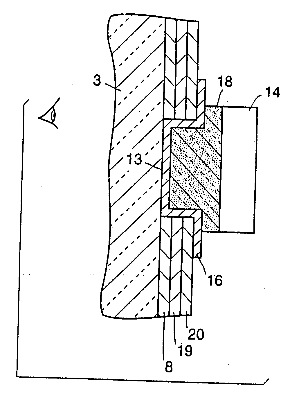
[0238] An electrochromic interior rearview automotive mirror cell having a shape commonly used for interior rearview mirrors was constructed from clear HW-ITO-coated glass as the first substrate (having a sheet resistance of about 12 ohms per square), with a tungsten oxide electrochromic solid film coated over its HW-ITO coating (which is coated onto the inward surface of the substrate). As the second substrate of the mirror cell, a HW-ITO-coated glass substrate (also having a sheet resistance of about 12 ohms per square) with the ITO coated onto its inward surface was used. A reflective element was formed by coating a layer of silver onto the rearmost (opposite, non-inward) surface of the second substrate of the mirror cell. The HW-ITO was coated onto the glass substrates at a thickness of about 1,500 Å; the tungsten oxide electrochromic solid film was coated over the HW-ITO coating of the first substrate at a thickness of about 5,000 Å; and the silver was coated onto the rearmost ...

example 2

[0250] In this example, we used the same electrolyte formulation and an electrochromic mirror constructed in the same manner as in Example 1, supra.

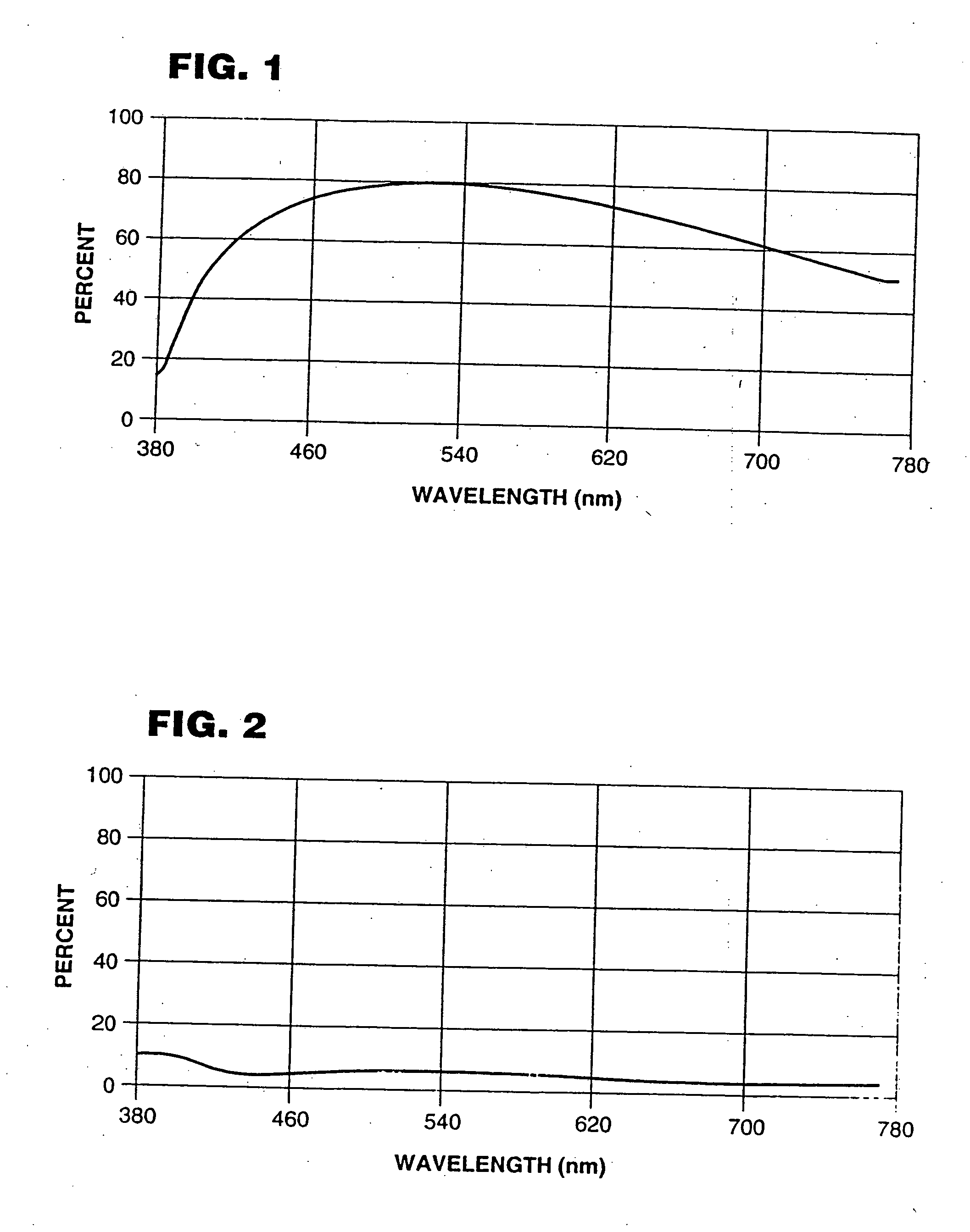
[0251] We introduced an applied potential of about 1.4 volts to the mirror and observed its center portion to change from a high reflectance of about 75.9% to a low reflectance of about 6.3%, which decreased from about 70% reflectance to about 20% reflectance in a response time of about 3.5 seconds.

[0252] We then subjected this mirror to an accelerated simulation of outdoor weathering conditions to investigate its resilience and stability to ultraviolet light. Specifically, we subjected the mirror to about 1300 KJ / m2 of ultraviolet exposure in an Atlas Ci35A Xenon Weather-o-meter (Atlas Electric Devices Company, Chicago, Ill.), equipped with a Xenon lamp emitting about 0.55 w / m2 intensity at about 340 nm. After accelerated outdoor weathering, we observed that the mirror continued to function suitably for use in a motor vehicle. We also...

example 3

[0254] The electrochromic mirror cell of this example was constructed from clear HW ITO-coated glass as the first substrate as in Example 1, supra. However, the second substrate was constructed of ordinary soda-lime glass. Using electron beam evaporation in a vacuum chamber, a layer of chromium was coated directly onto the inward surface of the second glass substrate as an adhesion promoter. Next, and without breaking vacuum, a thin film of silver was coated onto the layer of chromium as a reflective element, and thereafter (again without breaking vacuum) tungsten oxide was coated over the layer of silver as an electrochromic solid film. The layer of chromium was coated onto the second substrate at a thickness of about 1,000 Å; the thin film of silver was coated over the chromium at a thickness of about 1,000 Å; and the tungsten oxide was coated over the silver at a thickness of about 5,000 Å. The sheet resistance of the silver so undercoated with chromium was about 0.4 to 0.5 ohms ...


PUM

PropertyMeasurementUnit
areaaaaaaaaaaa
visible light reflectanceaaaaaaaaaa
wavelengthaaaaaaaaaa

Abstract

An electrochromic rearview mirror element for a motor vehicle comprises a first substantially transparent front substrate having a first and a second surface (and with a substantially transparent conductive electrode on its second surface) and a rear substrate having a third and a fourth surface. The rear substrate is positioned in spaced-apart relationship with the front substrate and with its third surface opposing the second surface of the front substrate. A mirror reflector is disposed on the third surface and a seal is positioned toward a peripheral edge of the substrates forming a cavity therebetween. An electrochromic medium is disposed in the cavity. The mirror reflector preferably comprises a metal layer that reflects at least about 70% of visible light. A display device can be disposed behind the rear substrate. The display device preferably exhibits, when electrically powered, a display luminance of at least about 30 foot lamberts as measured with the display device placed behind, and emitting light through, the electrochromic medium and with the electrochromic medium in its bleached state.

Description

RELATED UNITED STATES PATENT APPLICATION [0001] This application is a continuation-in-part of U.S. patent application Ser. No. 08 / 238,521, filed May 5, 1994.BACKGROUND OF THE INVENTION [0002] 1. Technical Field of the Invention [0003] The present invention relates to electrochromic devices for continuously varying the transmissivity to light suitable for use in, for example, electrochromic rearview mirrors, windows and sun roofs for motor vehicles, manufactured from electrochromic solid films and electrolytes containing redox reaction promoters and alkali ions and / or protons. [0004] 2. Brief Description of the Related Technology [0005] Prior to the introduction of electro-optic mirrors into the automotive marketplace, prismatic rearview mirrors were available to drivers of motor vehicles to determine the whereabouts of neighboring motor vehicles to their rearward surroundings. By using a manual lever located on such mirrors, a driver of a motor vehicle, especially at dusk or later, ...

Claims


Application Information

Patent Timeline
Patent Type & Authority Applications(United States)
IPC IPC(8): G02B17/00G02B5/08B05D5/00B05D5/06B05D5/12B32B17/06B60J3/04B60R1/08B60R1/12G02F1/1516G02F1/1524
CPCB32B17/06B32B17/10036B32B17/10293B60J3/04B60Q1/2665B60R1/04B60R1/12B60R1/088B60R1/1207B60R2001/1215G02F1/15G02F1/1523G02F1/1525B60R1/082B32B17/10513G02F1/1516G02F1/1524
Inventor V. VARAPRASAD, DESARAJUHABIBI, HAMIDA. MCCABE, IANR. LYNAM, NIALLZHAO, MINGTANGA. DORNAN, CRAIG
Owner DONNELLY CORP
Why Eureka
Try Eureka