Fisheye lens and imaging device using it

a technology of fisheye lens and imaging device, which is applied in the field of fisheye lens, can solve the problems of affecting the image quality of the whole imaging device, and increasing the field of view and image processing, so as to achieve compactness of the entire imaging device and improve optical performan

Active Publication Date: 2006-05-16
FUJI PHOTO OPTICAL CO LTD
View PDF4 Cites 102 Cited by
  • Summary
  • Abstract
  • Description
  • Claims
  • Application Information

AI Technical Summary

Benefits of technology

[0006]The present invention relates to a fisheye lens with a field of view of at least one hundred sixty degrees, having a bright image with an f-number in the range of 1.2 to 1.65, having superior optical performance, and that is compact. The present invention further relates to an imaging device that uses such a fisheye lens in order to achieve desirable properties related to the use of such a fisheye lens, including compactness of the entire imaging device.

Problems solved by technology

These fisheye lenses, which may be used in video imaging devices, form images on a single picture surface, which may be circular in shape, with high distortion aberration so that areas as well as the borders of the image are distorted, along with increasing the field of view and the need for image processing.
However, neither of these publications describes fisheye lenses with satisfactory off-axis performance.
In particular, all the aberrations in the fisheye lenses described in Japanese Laid-Open Patent Application S53-083623 are large, and none of these lenses meet the current requirements for achieving high performance.

Method used


Image

  • Fisheye lens and imaging device using it
  • Fisheye lens and imaging device using it
  • Fisheye lens and imaging device using it

Examples


embodiment 1

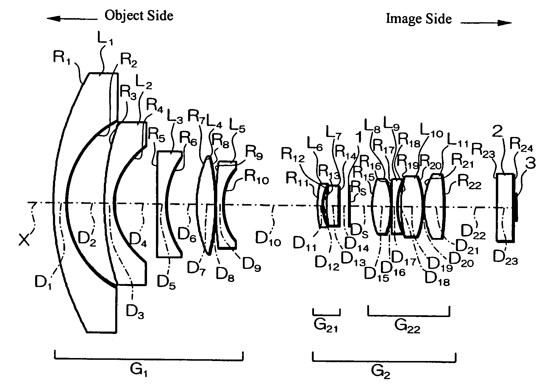
[0049]FIG. 1 shows a cross-sectional view of the fisheye lens of Embodiment 1 of the present invention. As shown in FIG. 1, the fisheye lens of Embodiment 1 includes, arranged in order from the object side, a first lens group G1 that includes five lens elements, L1–L5, and a second lens group G2 that includes, arranged in order from the object side, two lens elements, L6 and L7, that form a lens group G21, a stop 1, and lens elements L8–L11 that form a lens group G22. In Embodiment 1, all the lens elements are lens components.

[0050]Table 1 below lists the surface number # (except for the stop, which is listed as ‘Stop’) in order from the object side, the radius of curvature R (in mm) of each surface, the on-axis surface spacing D (in mm), as well as the refractive index Nd and the Abbe number vd (both at the d-line of 587.6 nm) of each optical element for Embodiment 1. Listed in the bottom portion of Table 1 are the focal length f, the f-number FNO, the half-field angle ω, the back ...

embodiment 2

[0057]Embodiment 2 is very similar to Embodiment 1 and uses the same number of lens elements and lens components. Because Embodiment 2 is very similar to Embodiment 1, Embodiment 2 is well shown by FIG. 1 and the differences between Embodiment 2 and Embodiment 1 will be evident from Table 3 that follows.

[0058]Table 3 below lists the surface number # (except for the stop, which is listed as ‘Stop’) in order from the object side, the radius of curvature R (in mm) of each surface, the on-axis surface spacing D (in mm), as well as the refractive index Nd and the Abbe number vd (both at the d-line of 587.6 nm) of each optical element for Embodiment 2. Listed in the bottom portion of Table 3 are the focal length f, the f-number FNO, the half-field angle ω, the back focal length bf, the on-axis distance EXP from the image plane to the exit pupil, and the on-axis distance Ds from the object-side surface of the object-side lens element of the fisheye lens to the image-side surface of the ima...

embodiment 3

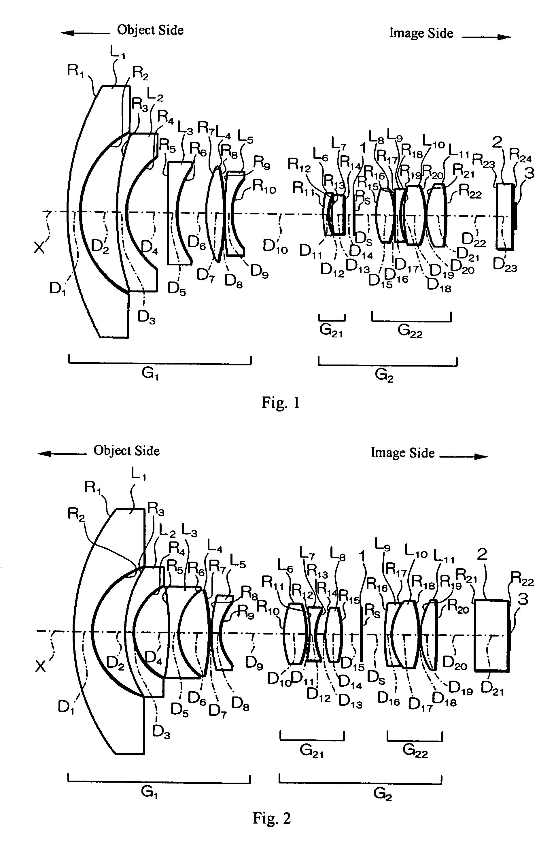
[0065]FIG. 2 shows a cross-sectional view of the fisheye lens of Embodiment 3 of the present invention. Embodiment 3 is similar to Embodiment 1 and uses the same number of lens elements but a fewer number of lens components. As shown in FIG. 2, the fisheye lens of Embodiment 3 includes, arranged in order from the object side: a first lens group G1 that includes five lens elements, L1–L5; and a second lens group G2 that includes, arranged in order from the object side, three lens elements, L6–L8, that form a lens group G21, a stop 1, and lens elements L9–L11 that form a lens group G22. Because Embodiment 3 is very similar to Embodiment 1, the differences between Embodiment 3 and Embodiment 1 will be evident from Table 5 that follows.

[0066]Table 5 below lists the surface number # (except for the stop, which is listed as ‘Stop’) in order from the object side, the radius of curvature R (in mm) of each surface, the on-axis surface spacing D (in mm), as well as the refractive index Nd and...


PUM


Abstract

A fisheye lens with a field angle of at least one hundred sixty degrees is formed of two lens groups, arranged in order from the object side, as follows: a first lens group having negative refractive power and a second lens group having positive refractive power. The first lens group includes, arranged in order from the object side, two lens elements, each having negative refractive power and a meniscus shape with the convex surface on the object side, a lens element having negative refractive power with a concave surface on the image side, and two lens elements of opposite refractive powers. The second lens group includes, arranged in order from the object side, two lens elements of opposite refractive powers, a stop, and two lens elements of opposite refractive powers. The fisheye lens preferably satisfies specified conditions related to spacings of lens surfaces and to distortion characteristics of the fisheye lens.

Description

FIELD OF THE INVENTION[0001]The present invention relates to fisheye lenses with equidistant image projections and to imaging devices that use such fisheye lenses. The present invention particularly relates to fisheye lenses that are optimally used to form images in imaging devices, including imaging devices that record images and / or are used for surveillance.BACKGROUND OF THE INVENTION[0002]Fisheye lenses with a field angle, that is, an entire picture angle, of nearly one hundred eighty degrees are known. These fisheye lenses, which may be used in video imaging devices, form images on a single picture surface, which may be circular in shape, with high distortion aberration so that areas as well as the borders of the image are distorted, along with increasing the field of view and the need for image processing. Furthermore, using computer software, modern techniques for removing distortion aberration that appears in images encourages greater use of fisheye lenses.[0003]On the other ...

Claims


Application Information

Patent Timeline
Patent Type & Authority Patents(United States)
IPC IPC(8): G02B13/06G02B13/04
CPCG02B13/06
Inventor NAKAYAMA, TORU
Owner FUJI PHOTO OPTICAL CO LTD
Why Eureka
Try Eureka