Four-color LED light mixing method based on visible light communication

A technology of visible light communication and light mixing, which is applied in the field of wireless optical communication, can solve the problems that do not consider the needs of communication, the system design has not yet appeared, and the control of lighting indicators is not considered.

Active Publication Date: 2014-09-17
SOUTHEAST UNIV
View PDF4 Cites 25 Cited by
  • Summary
  • Abstract
  • Description
  • Claims
  • Application Information

AI Technical Summary

Problems solved by technology

[0007] At present, the lighting research and the design of lighting quality control generally do not consider the needs of communication; and the multi-color mixed visible light communica...

Method used


Image

  • Four-color LED light mixing method based on visible light communication
  • Four-color LED light mixing method based on visible light communication
  • Four-color LED light mixing method based on visible light communication

Examples


Embodiment 1

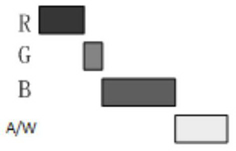
[0116] refer to Figure 1b , in the serial mode, only the time pulse width of each monochromatic light is adjusted. According to the obtained [k 1 ,k 2 ,k 3 ,k 4 ], adjust the corresponding light-emitting time pulse width of each monochromatic light, and obtain the target mixed white light at the emission end.

[0117] i. First calculate the response current I of the APD at the receiving end when each monochromatic light is emitted respectively si . It is known that the response function when the APD gain at the receiving end is 1 is R(λ). Considering the spatial positions of the receiving end and the transmitting end, there is

[0118] I si = ( m + 1 ) A 2 πd 2 cos m ...

Embodiment 2

[0142] refer to Figure 1c , In the serial mode, each monochromatic photocurrent and luminous time pulse width can be adjusted. According to the obtained [k 1 ,k 2 ,k 3 ,k 4 ] to adjust the ratio between the monochromatic photocurrent and the luminous time pulse width. Assume that the pulse width of each monochromatic light emitting time is x i , the ratio of the current relative to the 700mA drive current is y i , then there is the following relationship:

[0143] x i the y i =k i

[0144] i. First calculate the response current I of the APD at the receiving end when each monochromatic light is emitted respectively si . It is known that the response function when the APD gain at the receiving end is 1 is R(λ). Considering the spatial positions of the receiving end and the transmitting end, there is

[0145]

[0146] in,

[0147] M is the output gain of APD (take M=50);

[0148] m = - ln ...

Embodiment 3

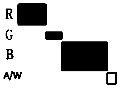
[0176] refer to Figure 1a , in parallel mode according to the obtained [k 1 ,k 2 ,k 3 ,k 4 ], adjust the corresponding bias current of each monochromatic light, and obtain the target mixed white light at the emission end.

[0177] i. First calculate the response current I of the APD at the receiving end when emitting different monochromatic lights si . It is known that the response function when the APD gain at the receiving end is 1 is R(λ). Since a variety of monochromatic lights are sent and mixed with white light at the same time, there is crosstalk at the receiving end, so filters are needed to filter the colors. Suppose the filter function of the filter is F i (λ), the response function of the APD at the receiving end is R(λ). Considering the spatial position of the receiving end and the transmitting end, as well as the cross-interference between different lights, there is

[0178]

[0179] In order to send j color light, the response current obtained through...


PUM


Abstract

The invention discloses a four-color LED light mixing method based on visible light communication. The method comprises the steps that spectral power distribution of all monochromatic light is obtained through a spectrograph, and the tristimulus value of each corresponding monochromatic light is calculated; the target color temperature of mixed light is determined, and a corresponding reference light source is selected and used for obtaining the tristimulus value of a mixed color; according to the color addition principle, the sum of the tristimulus values of all the monochromatic light should be equal to the tristimulus value of the mixed color, and a color mixing equation set is obtained; the spectral power distribution of the mixed light can be obtained according to the light mixing coefficient of all the monochromatic light in the color mixing equation set, and the color rendering index Ra of the mixed light is calculated according to the spectral power distribution of the mixed light, wherein Ra is larger than or equal to epsilon; the range of the channel capacity C of the mixed light is calculated, and the maximum capacity Cmax is solved within the range; the ratio of all the colored light with the maximum capacity is output.

Description

technical field [0001] The invention belongs to the technical field of wireless optical communication, and in particular relates to a four-color LED light mixing method based on visible light communication. Background technique [0002] With the continuous development of social economy, people's requirements for the quality of life are getting higher and higher. At the same time, the communication field begins to pursue a "green" and "high-speed" communication technology. Visible light communication technology, as an alternative to the above, is gradually becoming a hot spot in the research field. It uses laser devices or LED devices to achieve high-speed information transmission through modulation of light intensity, which meets people's requirements for high-speed information transmission while meeting daily work lighting. This technology has the advantages of free broadband spectrum resources independent of radio frequency spectrum, no electromagnetic interference and ra...

Claims


Application Information

Patent Timeline
IPC IPC(8): H05B37/02F21V9/10F21S10/02F21Y101/02F21V9/40F21Y115/10
CPCY02B20/42Y02B20/40
Inventor 梁霄吕游王家恒赵春明
Owner SOUTHEAST UNIV
Why Eureka
Try Eureka